• The move to the new server is done. There are some software and database maintenance updates in process. This has us passing the hat around to help out. We appreciate any donations. Seriously, even a dollar helps. The payment page may be found here - https://www.audiokarma.org/support.html

Dynaco Dynakit St-70 rebuild thread

what he said, per-channel. The match is more important than the actual value here.


honestly I'm surprised it doesn't already exist. I know solid state plug-in rectifiers are out there now, and some apparently have drop resistors. If they'd just tell you what the resistor was, then you could simply buy the thing. I'm cheap though, and I just couldn't pay actual money for something I can throw together for a couple minutes using parts in the junk box.


wouldn't want to put that much voltage on that switch, and I wouldn't want it something that could accidentally be flipped the wrong way.


I was thinking only voltage switch would see the drop amount the resistor would have made up for the lower v drop of the SS diode.
Also I was thinking you'd only change in an unenergized condition.
I'm not looking to change mine. It was just a suggestion of flexibility. Most people don't use the amp in mono.
 
For sake of conversation. Its probably a bad idea in practice (repurposing stereo/mono switch ) to bypass dropping resistor.
For sake of practice. The switch (at least the replacement) is rated 125vac at 3A (each contact).
I tend to doubt there's any conversion to a DC rating.
I think in the context of the previous post thought is with 500v (+/- DC?) to ground , there's potential (no pun intended) to arc over to the grounded case of the switch.
A little research, seems to show needing 30kv to jump a 1 cm gap and or 1.1kv to jump a 1 mm gap. (Dry conditions, less to maintain after ionization).
My "guess " is it'd work fine as I suggested.
Kind of a moot point if a SS plug in rectifier works better and you already have the resistor installed.
Also if you were to sell, it'd be a good idea to explain what you did or better still undo it.
:idea:
 
most of that is about what it can break reliably. It matters less if you don't switch it in operation, at that point its basically just a terminal strip. I still just don't like the idea of HV being on that switch. Not sure what the insulation to ground is rated for, especially after 50 years of dirt and contact cleaner exposure.
 
As far as THIS thread goes, I’d like to keep the chassis pretty stock—so the idea of having a plug in tube socket rectifier with resistors as part of the assembly, such that no permanent mod has happened to chassis—is very exciting.

I’d prefer not to repurpose switches on the chassis if possible.
 
so I had another thought about this. if you make your own plug-in SS rectifier, who says the output has to be on pin 8? Why not bring it out on pin 3 or 1, and put the resistor underneath from that pin to 8? That would allow vacuum rectifier or SS use with no special tricks required. It also allows the yellow sheet mod to work.
 
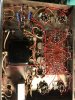
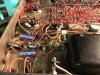
Progress underneath.

Dynakitparts selenium rectifier kit, wider rca jack kit, and replacement stereo mono switch.

Two 10ohm resistors short in my order, need to check my spare parts. And need one more pair of matched 47k resistors for the pcb, wanted to check that before trimming all of those leads.
 

Attachments

  • 863D5B64-360A-4E32-B9E8-D52B61A1AE20.jpeg
    863D5B64-360A-4E32-B9E8-D52B61A1AE20.jpeg
    87.6 KB · Views: 78
  • C20A6F5C-CB4B-4C1E-BB76-524A66091955.jpeg
    C20A6F5C-CB4B-4C1E-BB76-524A66091955.jpeg
    121.8 KB · Views: 71
  • 6AF1AEFA-5E2D-451E-ABCB-2F3A4D2E284B.jpeg
    6AF1AEFA-5E2D-451E-ABCB-2F3A4D2E284B.jpeg
    119.4 KB · Views: 74
  • 23956A4B-7962-443C-9694-7528B545D39F.jpeg
    23956A4B-7962-443C-9694-7528B545D39F.jpeg
    58.7 KB · Views: 74
Why would the resistor heat be more of a concern on top of the chassis than below?

If you did not enclose the tube base, so the heat could escape out of the top, what would the risk be?

Is the resistor heat more significant than a hot tube?

^^ yes, that.

I'd be tempted (half because I do things like this) to construct that in a plug-in octal device so the amplifier itself remains unmodified. The trick I suppose is dealing with the heat. Maybe a chassis-mount type attached to the inside of a tube could work, but really it would want to have a flat spot inside to mount the resistor on. Just having it touch at the very edges won't be too effective.
 
Why would the resistor heat be more of a concern on top of the chassis than below?

If you did not enclose the tube base, so the heat could escape out of the top, what would the risk be?

Is the resistor heat more significant than a hot tube?
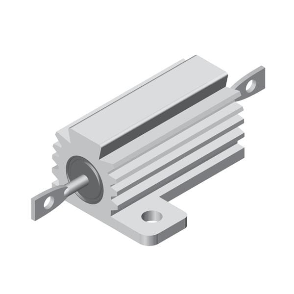
It's generally a good idea to have heat-producing devices be out in the open, rather than letting the heat they produce be confined to the underside of a chassis where it might have an adverse effect on any nearby parts which might be heat-sensitive (particularly electrolytic capacitors). That's why vacuum tubes (usually) sit on the top of the chassis rather than being tucked underneath. Something along the lines of this or this might be the best option if the resistor in question absolutely must live underneath the chassis:
HS_series_DSL.JPG
RHNH_RE_Military_DSL.jpg

(generic photos, but both Ohmite and Dale make finned resistors which look like this)
 
I was suggesting the opposite—that the diodes and resistor could live in an octal base on top of the chassis. Open on top to breathe.

It's generally a good idea to have heat-producing devices be out in the open, rather than letting the heat they produce be confined to the underside of a chassis where it might have an adverse effect on any nearby parts which might be heat-sensitive (particularly electrolytic capacitors). That's why vacuum tubes (usually) sit on the top of the chassis rather than being tucked underneath. Something along the lines of this or this might be the best option if the resistor in question absolutely must live underneath the chassis:
HS_series_DSL.JPG
RHNH_RE_Military_DSL.jpg

(generic photos, but both Ohmite and Dale make finned resistors which look like this)
 
I was suggesting the opposite—that the diodes and resistor could live in an octal base on top of the chassis. Open on top to breathe.
Just figured I'd mention that style of resistor as an option. Besides, they're not a bad idea anyway, since there's plenty of metal there to attach them to.
-Adam
 
basically its just one of air space. If you enclose it totally, the heat will build up in the small space inside the octal plug-in. If you don't use something that can stand the heat it might melt. Don't put that in PVC pipe for example. Metal would work though. Under the chassis the heat at least has some space to radiate into, though if you can not put the heat there or put it directly into the metal chassis you're ahead of the game.
 
For sake of responding, this is the one i used. Assuming they're just diodes in an octal socket, i suspect they're all the same.
https://www.ebay.com/p/Solid-State-...MIjM_IjcLG4wIVko7ICh01cg28EAkYBSABEgJGP_D_BwE

I wouldn't be surprised at all if these are all the same product with different lableing
https://tubedepot.com/products/soli...MIjM_IjcLG4wIVko7ICh01cg28EAkYASABEgIlmvD_BwE

https://www.opentip.com/search.php?...MIjM_IjcLG4wIVko7ICh01cg28EAkYAiABEgLW2vD_BwE

https://reverb.com/item/17156990-br...h01cg28EAkYCCABEgLSsvD_BwE&gclsrc=aw.ds&pla=1

no affiliation with any product or source
 
Last edited:
Seems like I may be in the home stretch here...trimmed all the leads, need to get some new 1% 47k resistor pairs for the board but otherwise just the can cap replacement and tubes and rectifier left to go....

Can Cap:
there seem to be three options:

original spec 40/20/20/20 @ 525 vdc
upped uf 80/40/30/20 @ 525 vdc
upped uf and V 80/40/30/20 @ 550vdc with 600 v surge capacity

some people claim improved sound for the second option, minor cost difference.
Is there anything in the use of a solid state rectifier that would stress the can caps, or is it just the coupling caps people are concerned with? The third option is significantly more expensive than the first two?

Rectifier:
@noveltone is going to help me out with a ss rectifier with heat sink and resistor in an octal base that will be a plug in replacement. It's going to be incredible. He'll probably patent it and produce it and make tens of dollars selling them on this website!
We will let everyone knows how it goes.

Tubes:
I was thinking JJ EL34 or E34L's, both seem to have their fans. Anyone here have strong feelings one way or the other?
 
so I had another thought about this. if you make your own plug-in SS rectifier, who says the output has to be on pin 8? Why not bring it out on pin 3 or 1, and put the resistor underneath from that pin to 8? That would allow vacuum rectifier or SS use with no special tricks required. It also allows the yellow sheet mod to work.
You should draw it up and call it say, the "Green Sheet" mod. And see how often it pops up over time. :D
 
Back at it.
Matched 47k resistors and can cap showed up.
(And tubes and ss rectifier)

FWIW, desoldering crusty old cloth wrapped transformer leads was the most unsettling part of this project so far. Are there any tricks there? I assume clipping them and restripping would get messy?
 

Attachments

  • 0257EAF7-F754-4A8F-B900-49AA20F2C7CD.jpeg
    0257EAF7-F754-4A8F-B900-49AA20F2C7CD.jpeg
    114.7 KB · Views: 53
clipping and stripping might actually be less of a problem. Not so much risk of the plastic insulation inside the cloth melting that way.
 
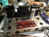
Used the recommended 80uf towards the back orientation on the upgrade can cap and I believe everything is back where it should be, but let me know if anything looks amiss.
 

Attachments

  • 63A25B8C-D944-44F7-9702-0871818F4977.png
    63A25B8C-D944-44F7-9702-0871818F4977.png
    268.3 KB · Views: 50
  • BE1B3951-63B9-4DC6-BC37-3AC98494D34E.jpeg
    BE1B3951-63B9-4DC6-BC37-3AC98494D34E.jpeg
    133.9 KB · Views: 50
  • 84C06695-5DE7-49A2-B502-8C4CEC175656.jpeg
    84C06695-5DE7-49A2-B502-8C4CEC175656.jpeg
    117.8 KB · Views: 51
If none of the wire strands are broken off,

I'm more used to point to point wiring, so when I'm undoing transformer leads, its usually from a tube socket. IME the heat and time involved to get wires unsoldered causes more damage, and half the time you can't re-use the mess that comes out anyway. Its just easier for me to clip the wire right at the insulation, remove the old strands, then strip and re-solder when its time to do that. On a circuit board its not a big deal though.
 
Back
Top Bottom