

You are using an out of date browser. It may not display this or other websites correctly.
You should upgrade or use an alternative browser.
You should upgrade or use an alternative browser.
Dynaco Dynakit St-70 rebuild thread
- Thread starter hrtattckcity
- Start date
-
- Tags
- dynaco st-70 dynakit st70


nj pheonix
Lunatic Member
Easier to work on if you pull it
This might make your life easier.


note the first image is upside down to the second
This might make your life easier.
note the first image is upside down to the second
Last edited:

GuyNoir
Hallowed State
(SNIP) does everyone tend to agree the 6gh8a is a suitable replacement?
This video may interest you.

I've mentioned this elsewhere, but I have some questions about that video. On the surface it makes it sound like the 7199 is the only right choice. The trick here is that the characteristics of the pentode section affect the phase inverter balance. Slight screen voltage differences change the plate voltage, and the plate voltage affects the triode section since they are direct coupled. Upset that balance and you get unequal drive from the inverter, and unequal drive from the inverter increases distortion. I strongly suspect (but don't own an ST-70 to test this on) that if you tweak the screen resistor to get the plate of a 6GH8 at stock specs, you'd find the THD figures to be very comparable.
GuyNoir
Hallowed State
My takeaway, in his closing statements, was that one of the 6U8A tubes he tested was at least as good as the 7199, and I remember him saying he thought that one of the 6U8A he tested was probably suspect.I've mentioned this elsewhere, but I have some questions about that video. On the surface it makes it sound like the 7199 is the only right choice.
nj pheonix
Lunatic Member
I got that takeaway also. While tweaking the resistor value may in fact improve the distortion #s, i wasn't getting the impression the host was suggesting that and it seemed all the tubes (except the suspect one performed fine. )
Thain,
If you're curious, i'll lend you my ST70 (built to Dave's design suggestions in the baseline thread), some 7199s, some adaptors, and some 6gh8s. I'm pretty sure i have no 6u8s. Open offer if you're interested.
Thain,
If you're curious, i'll lend you my ST70 (built to Dave's design suggestions in the baseline thread), some 7199s, some adaptors, and some 6gh8s. I'm pretty sure i have no 6u8s. Open offer if you're interested.
If you're curious, i'll lend you my ST70 (built to Dave's design suggestions in the baseline thread), some 7199s, some adaptors, and some 6gh8s. I'm pretty sure i have no 6u8s. Open offer if you're interested.
I have a pile of them. I can send you some if you're up for fooling with it. I got no AC in the shop, so I make efforts to avoid the area during the summer.
How does a change in the plate voltage of the pentode section (directly coupled to the grid of the triode section) affect the phase inverter balance? Does it offset the Q-point of the triode section? I thought all you need for this cathodyne phase inverter are closely matched resistors in the triode section's plate and cathode to get balanced phase inverter output?
Basically when you change the grid voltage it changes the bias point. Too far off and it can clip positive or negative, depending on which direction its wrong at, and that will give uneven grid drive. I doubt you'd ever notice it at low power but it could be an issue at higher output levels. If its way off you could have the triode out of the linear zone and that could add some distortion too I suppose.
The proper plate voltage has more to do with what the grid voltage of the triode section needs to be. If you target what Dynaco says the plate of the pentode should be, it ought to be very close to right. Maybe if you want to get more detailed with it, do the load line calcs for the triode section in each tube, and use that to set the pentode voltage. Messing with the screen voltage is the easiest way to tweak that.
feh, didn't realize the manual didn't have that infio
Dynaco ST-70: Base Line Testing
has a lot more detail, but the nuts and bolts conclusion seems to be that the plate of the pentode should be right around 110v.
Dynaco ST-70: Base Line Testing
has a lot more detail, but the nuts and bolts conclusion seems to be that the plate of the pentode should be right around 110v.
nj pheonix
Lunatic Member
Again,
Watching the video as a believer (I tend to be a skeptic when watching those sort of things. Only because they're generally hawking some unproven thing without any real explanation why what they're trying to prove is better. Or they're trying to sell you something).
Watching this particular video (my take). Guy seemed knowledgeable enough, and well equipped enough to run the test he was trying to do (me , I would've run it at 115-117v but that's nitpicking and I doubt the results would have been different. Just the operating point the st70 was designed to run at.
Some tube operating points can be critical in certain circuits. Less so in others. I'm clearly not savvy enough to say how critical this application is. My guess is , it isn't too critical, based on the the fact that the dynaco was a kit. It didn't spec 5 or 1% resistors (well maybe that oddball bias resistor).
Watching 3 similar tubes (yes the amp wasn't specifically meant to run all 3) run through the 3 sweeps on 2 channels all returned remarkably similar traces (again except for the oddball tube).
I also remember Dave mentioning I think it was a Scott that used a 7199 and the 6gh8 wasn't a suitable sub).
If you owned one and wanted to play and had a stack of either of the other tube replacements, I guess you could possibly dial the distortion in better.
I've certainly gone through pieces and replaced every 10% carbon comp with 1% (and even went through the trouble of matching them channel to channel). I'd be lying if I told you it made the piece sound better when it's done (unless something was out of spec when I started. I think most people who have taken stuff apart have done this at least once.
Based on the video ( shouldn't be your only source of reference) I doubt subbing these tubes will alter the sound of the ST70.)
Tweaking the amp with the subs may improve ultimate measured distortion, I tend to doubt will wake it audibly different.
Last edited:
Most of the technical conversation is beyond me, not that I mind it.
This conversation is in part what left me to use the original board with the slightly less cost effective tube adapters-so if someone else had this down the line and wants to chase down 7199’s they can. And in part I liked the idea of keeping the original board cosmetically, if it holds together.
On a practical note—is everyone running their st-70s on 115v? Are you using a buck transformer or Variac all the time? What’s the best/cheapest way to do this?
nj pheonix
Lunatic Member
I clearly stand corrected 

Maybe I should shut up
All I've based my comments on is other peoples tests and observations.
In case it came off that way, I wasn't disagreeing with gadget.
Merely stating (based on what others have written before) there's likely little to be gained by tweaking the resistor values here.
Hey , I've been wrong before. Offer is open to Gadget come the cooler weather (if he feels so inclined)
On a practical note—is everyone running their st-70s on 115v?
Poke a voltmeter into one of the front sockets from pin 1 to 2. The manual calls for 6.4 vac there. As long as its below 6.7 vac, you're fine. If the heater string doesn't land there, you can measure from pin 2 to 7 on the EL34 socket, but it needs to be done with all tubes installed. Bit safer using the front connector.
If too high, an old transformer with a 6-10v winding can be used as a bucking transformer. Whatever the secondary voltage is how much your line voltage ends up knocked down. 6.3v filament transformers are pretty common but you can salvage stuff from assorted places.

noveltone
Active Member
I looked up the website and found this page interesting, where it says yellowjackets won't hurt your amp https://www.yellowjacketstc.com/more-information It states: "...all Yellow Jackets® converters internally limit voltage and current..." But, they are not very specific about what they mean/how this is done, and I don't know if they had audio amps like the Stereo 70 in mind. I'd want to see a schematic of the yellowjacket to see what it has inside it. If it is just two silicon diodes and nothing more, then you'd need the resistor Dave G. mentioned in order to reproduce the voltage drop of a 5AR4 rectifier. There would also still be the matter we've been discussing about the voltage rating of the coupling capacitors in relation to turn-on surges.
If the yellowjacket does include a resistor, then I'd want to take a reading to see exactly what voltage you get from it, though during such testing I'd want to reduce the AC power to the amp via a variac and take various readings to make sure the voltage ratings on the amplifier's components are not exceeded. Again, the point is that you want to reproduce the voltage drop of the tube rectifier while making sure that component ratings are not exceeded during testing or normal startup.
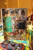
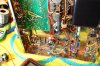
Getting back briefly to the power supply rectifier, I think Dave G's concern has more to do with power transformer currents having parity with original. If 600V caps are provided and tubes down't draw current until later, this seems to be a good approach. To avoid yellowjacket testing, Dave's approach was to use a simple SS rectifier and add the resistor manually as a 50R 10W. There is a nice straight wire if I understand correctly. Replace the jumper with a resistor (insulate leads), seems like a good approach right? See images for what I'm thinking.


nj pheonix
Lunatic Member
Don't have it in front of me but that looks correct
nj pheonix
Lunatic Member
 not sure this is clear. landed on T strip and extended with blue wire
Last edited:
^^ yes, that.
I'd be tempted (half because I do things like this) to construct that in a plug-in octal device so the amplifier itself remains unmodified. The trick I suppose is dealing with the heat. Maybe a chassis-mount type attached to the inside of a tube could work, but really it would want to have a flat spot inside to mount the resistor on. Just having it touch at the very edges won't be too effective.
I'd be tempted (half because I do things like this) to construct that in a plug-in octal device so the amplifier itself remains unmodified. The trick I suppose is dealing with the heat. Maybe a chassis-mount type attached to the inside of a tube could work, but really it would want to have a flat spot inside to mount the resistor on. Just having it touch at the very edges won't be too effective.
nj pheonix
Lunatic Member
You could make the stereo mono switch a bypass switch for the resistor and plug a tube in.

what he said, per-channel. The match is more important than the actual value here.
honestly I'm surprised it doesn't already exist. I know solid state plug-in rectifiers are out there now, and some apparently have drop resistors. If they'd just tell you what the resistor was, then you could simply buy the thing. I'm cheap though, and I just couldn't pay actual money for something I can throw together for a couple minutes using parts in the junk box.
wouldn't want to put that much voltage on that switch, and I wouldn't want it something that could accidentally be flipped the wrong way.
You'd make a fortune selling it as a "mod" for not only the original Dynacos but also for the Latino and Triode USA and maybe even the Van Alstine...
honestly I'm surprised it doesn't already exist. I know solid state plug-in rectifiers are out there now, and some apparently have drop resistors. If they'd just tell you what the resistor was, then you could simply buy the thing. I'm cheap though, and I just couldn't pay actual money for something I can throw together for a couple minutes using parts in the junk box.
You could make the stereo mono switch a bypass switch for the resistor and plug a tube in.
wouldn't want to put that much voltage on that switch, and I wouldn't want it something that could accidentally be flipped the wrong way.