• The move to the new server is done. There are some software and database maintenance updates in process. This has us passing the hat around to help out. We appreciate any donations. Seriously, even a dollar helps. The payment page may be found here - https://www.audiokarma.org/support.html

Dynaco Dynakit St-70 rebuild thread

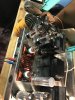
Hey guys, thought I was done...
Brought everything up on a variac and tubes were glowing (more or less all evenly), only getting sound out of one channel and nothing but some hum out of the other.
no smoke or anything obviously catastrophic.

Any thoughts on how best to start troubleshooting?
 
swap the driver tubes and see if anything changes.

if not, start checking voltages and comparing the working channel to the not-working one. Pretty fair bet one channel will have a big difference somewhere along the line.
 
swap the driver tubes and see if anything changes.

if not, start checking voltages and comparing the working channel to the not-working one. Pretty fair bet one channel will have a big difference somewhere along the line.

Doesn’t seem to be the driver tubes.

What is the proper procedure for checking voltages—tubes in/out? Rectifier in/out
Positive probe to test point per the schematic, negative to chassis?

I will go back through the manual and double check my wiring against the assembly instructions.
 
all tubes in, negative probe to chassis, pos to whatever the test point is.

Does it bias normally? If so, that tells me the voltages at the output stage are fine and your problem is someplace on the driver board. If it doesn't bias, then you've got something going on at the output tubes.
 
Seemed to bias all right; I was using a digital multimeter with only a 2 digit read out and it set to 1.6. I did not have it on long enough to re-check it, however.

all tubes in, negative probe to chassis, pos to whatever the test point is.

Does it bias normally? If so, that tells me the voltages at the output stage are fine and your problem is someplace on the driver board. If it doesn't bias, then you've got something going on at the output tubes.
 
Close enough. That means the output tubes are good, have voltage at the plate and screen, the cathode circuit isn't open, and the grid bias supply is of some reasonable level. That would point me at the driver board, or the connections in and out of it.
 
Are the affected channels entirely dead? It's always possible for one of the wires to experience an internal break if flexed too much. Dynaco supplied solid wire with the ST-70, and aside from the fact that it's well over 40 years old at this point, solid core wire doesn't take well to being moved around too much. Such a failure probably wouldn't show up in a voltage test if it's along the signal level, so you might need to use a continuity tester WITH THE AMPLIFIER TURNED OFF AND UNPLUGGED to check all the wires in the signal chain between the input jacks on the front and the input grid of the output tubes. Also check for broken traces on the driver board, bad solder joints at the eyelets where each wire connects to said board, and any ground wires associated with the signal. Good luck!
-Adam
 
Someone had asked about crosstalk, so I did put the preamp balance all the way to the humming channel--when the volume was turned up the hum volume did not increase but I could hear music faintly in the humming channel.

Are the affected channels entirely dead? It's always possible for one of the wires to experience an internal break if flexed too much. Dynaco supplied solid wire with the ST-70, and aside from the fact that it's well over 40 years old at this point, solid core wire doesn't take well to being moved around too much. Such a failure probably wouldn't show up in a voltage test if it's along the signal level, so you might need to use a continuity tester WITH THE AMPLIFIER TURNED OFF AND UNPLUGGED to check all the wires in the signal chain between the input jacks on the front and the input grid of the output tubes. Also check for broken traces on the driver board, bad solder joints at the eyelets where each wire connects to said board, and any ground wires associated with the signal. Good luck!
-Adam
 
oh, related external check, flip the two input cables at the front of the amp and see if the dead channel moves or stays dead. If it moves, its a problem outside of the amplifier.
 
Someone had asked about crosstalk, so I did put the preamp balance all the way to the humming channel--when the volume was turned up the hum volume did not increase but I could hear music faintly in the humming channel.
I'd still check for open connections as I detailed above. Also try the cable swap as gadget mentioned. I rather doubt that you're experiencing a major fault, just a rather annoying one.
-Adam
 
Voltage on pins 1&8 of the good channel are at 1.56, and 1.49 at the bad channel.

Bias sets to 1.56 ok.

Found a couple of questionable connections on the board and reflowed them, but no improvement yet.
 
And, working again.

I realize that there is probably a simple dumb mistake I am making. Loose wire. Something.

But both times it has started working properly I have had some paper cone drivers I pulled from a magnavox console hooked up, and then it can be switched to another set of speakers just fine.

I’m going to test it several more times before following up.
 
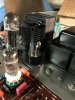
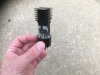
@noveltone came over last night and we tried out his plug-in octal solid state rectifier with built-in heat sink and resistor.

It’s a thing of beauty. And worked like a champ.
I’ll let him provide the details if anyone is interested. Or he can just hide it in a plastic tube filled with silica and Market it with a cool name?


^^ yes, that.

I'd be tempted (half because I do things like this) to construct that in a plug-in octal device so the amplifier itself remains unmodified. The trick I suppose is dealing with the heat. Maybe a chassis-mount type attached to the inside of a tube could work, but really it would want to have a flat spot inside to mount the resistor on. Just having it touch at the very edges won't be too effective.

Amp has been working great. Bias’s fine—I’ve been using @noveltone ’s Variac to keep things down to around 115, but will probably try it in a nornal outlet now that it’s all square.

Sounds great with the model 19’s I was working on.
 

Attachments

  • DEDBC9D7-B6CC-4724-A448-2391F0574215.jpeg
    DEDBC9D7-B6CC-4724-A448-2391F0574215.jpeg
    57.7 KB · Views: 113
  • 698B8241-4171-4991-B1F0-1E00B39E5F05.jpeg
    698B8241-4171-4991-B1F0-1E00B39E5F05.jpeg
    71.5 KB · Views: 120
  • 31DBC5A7-848F-4493-ABD2-A72C7B5F5D44.jpeg
    31DBC5A7-848F-4493-ABD2-A72C7B5F5D44.jpeg
    72.7 KB · Views: 115
  • 9F9277CA-5B83-45E7-B5CA-1490340E4BCC.jpeg
    9F9277CA-5B83-45E7-B5CA-1490340E4BCC.jpeg
    84.9 KB · Views: 113
Last edited:
I use the chop stick test

Take a wood chopstick and tap the solder joint connections to look for intermittent connections
especially after warm up

works for me
 
@noveltone came over last night and we tried out his plug-in octal solid state rectifier with built-in heat sink and resistor.

It’s a thing of beauty. And worked like a champ.
I’ll let him provide the details if anyone is interested. Or he can just hide it in a plastic tube filled with silica and Market it with a cool name?


Amp has been working great. Bias’s fine—I’ve been using @noveltone ’s Variac to keep things down to around 115, but will probably try it in a nornal outlet now that it’s all square.

Sounds great with the model 19’s I was working on.
That's the coolest looking SS rectifier I've ever seen.
 
Hey thanks @Lavane and @hrtattckcity. Here is some info about the parts I used. I got them from Digikey.
Diodes: Qty 3 Vishay VS-HFA06TB120-M3; HEXFRED 1.2KV 6A TO220AC, soft recovery types.
Resistor: Qty 1 Ohmite TNP10SC50R0FE; Thin Film 50Ω 10W TO-126. 10w only with heatsink.
Heat Sink: Qty 1 Wakefield-Vette/ OMNI-UNI-30-25-D
Insulators and shoulder washers, since tab of diodes is connected with cathode. Need to electrically insulate the diodes from the heatsink and from each other.
I used hollow eyelet rivets as vias in FR4 PCB material. PCB was cut to fit just inside tube base. I really like working with those rivets for one-off PCBs, available from Keystone.

Process: I soldered wires into the hollow pins in the octal tube base, left long. After I had soldered some parts on the board I placed the PCB into the tube base, running the wires from octal positions inputs (4,6) and output (8) up through the pcb. Did not use (2) which is the heater. Soldered and trimmed those. Make sure there is at least 1mm space between metal parts at different potentials to avoid high voltage arcing. For safety I added a wire to octal position 1 that connects to the heatsink. I think a person should add a wire connecting chassis ground to this #1 pin, so that if heatsink becomes live, it draws a fault before hurting someone.

Circuit: Based on some modeling using PSUD2, worst case inverse voltage at diodes is nearly 2,000V! My first pass at this...didn't make it, but didn't damage anything either. My solution was to add one diode after the primary two input diodes' cathodes are connected. My thinking is that at each AC cycle there would be two 1,200V-rated diodes in series. If they roughly share the current they could split the 2,000V worst-case and take 1,200V each. The resistor which mimics the tube's internal resistance is something I understand the least. I didn't have time to get into Spice, so its 50R value arrived at by doing iterations comparing tube and ss power supplies in PSUD2, can explain that more if anyone is interested. It might well be wrong, but that value was suggested by others here, so I felt OK proceeding.
It worked for us, maybe it will work for you. This is dangerous so if you get hurt, keep it to yourself!

 
Hey thanks @Lavane and @hrtattckcity. Here is some info about the parts I used. I got them from Digikey.
Diodes: Qty 3 Vishay VS-HFA06TB120-M3; HEXFRED 1.2KV 6A TO220AC, soft recovery types.
Resistor: Qty 1 Ohmite TNP10SC50R0FE; Thin Film 50Ω 10W TO-126. 10w only with heatsink.
Heat Sink: Qty 1 Wakefield-Vette/ OMNI-UNI-30-25-D
Insulators and shoulder washers, since tab of diodes is connected with cathode. Need to electrically insulate the diodes from the heatsink and from each other.
I used hollow eyelet rivets as vias in FR4 PCB material. PCB was cut to fit just inside tube base. I really like working with those rivets for one-off PCBs, available from Keystone.

Process: I soldered wires into the hollow pins in the octal tube base, left long. After I had soldered some parts on the board I placed the PCB into the tube base, running the wires from octal positions inputs (4,6) and output (8) up through the pcb. Did not use (2) which is the heater. Soldered and trimmed those. Make sure there is at least 1mm space between metal parts at different potentials to avoid high voltage arcing. For safety I added a wire to octal position 1 that connects to the heatsink. I think a person should add a wire connecting chassis ground to this #1 pin, so that if heatsink becomes live, it draws a fault before hurting someone.

Circuit: Based on some modeling using PSUD2, worst case inverse voltage at diodes is nearly 2,000V! My first pass at this...didn't make it, but didn't damage anything either. My solution was to add one diode after the primary two input diodes' cathodes are connected. My thinking is that at each AC cycle there would be two 1,200V-rated diodes in series. If they roughly share the current they could split the 2,000V worst-case and take 1,200V each. The resistor which mimics the tube's internal resistance is something I understand the least. I didn't have time to get into Spice, so its 50R value arrived at by doing iterations comparing tube and ss power supplies in PSUD2, can explain that more if anyone is interested. It might well be wrong, but that value was suggested by others here, so I felt OK proceeding.
It worked for us, maybe it will work for you. This is dangerous so if you get hurt, keep it to yourself!
Bookmarked, thanks. :thumbsup:
 
Back
Top Bottom