• The move to the new server is done. There are some software and database maintenance updates in process. This has us passing the hat around to help out. We appreciate any donations. Seriously, even a dollar helps. The payment page may be found here - https://www.audiokarma.org/support.html

Dynaco Mark III Classroom

Donstaff

Active Member
After dabbling in kit building over 50 years ago with early HeathKit transistor amp and tuner kits, then building a Dynaco SCA-80, SCA-50, and FM-5, I am at long last trying to understand how these thing work. I've always loved Dynaco, especially in light of the fact that all three of the kits that I built in my 20s still work fine after 50 years and thousands of hours. I have a Dynaco Mark III that I bought on eBay about 30 years ago but never hooked up. I'd like to use it as a tool for learning something about troubleshooting and restoration.

At this point, I don't know whether the Mark III works at all, or if does, to what degree. I've never been a technician, but I'd like to learn a little about troubleshooting and restoration. Armed only with a signal oscillator and a 50k ohm/volt DC - 20k ohm/volt AC volt ohm meter, I'd like to see what I can learn.

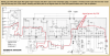
On background, I have a Dynaco PAT-5 schematic on which Dan, of Updatemydyna.com, has traced out the path of a signal that was applied to the tuner input. (See attached). To get started, I'd really appreciate it if someone could similarly trace the signal path on the attached schematic for the Mark III tube amp. This could be fun!

Thanks,

Don
 

Attachments

  • Screen Shot Dynaco Mark III.png
    Screen Shot Dynaco Mark III.png
    164 KB · Views: 70
  • Screen Shot Dynaco PAT-5 sig path.png
    Screen Shot Dynaco PAT-5 sig path.png
    329.9 KB · Views: 65
Register to hide this ad
After dabbling in kit building over 50 years ago with early HeathKit transistor amp and tuner kits, then building a Dynaco SCA-80, SCA-50, and FM-5, I am at long last trying to understand how these thing work. I've always loved Dynaco, especially in light of the fact that all three of the kits that I built in my 20s still work fine after 50 years and thousands of hours. I have a Dynaco Mark III that I bought on eBay about 30 years ago but never hooked up. I'd like to use it as a tool for learning something about troubleshooting and restoration.

At this point, I don't know whether the Mark III works at all, or if does, to what degree. I've never been a technician, but I'd like to learn a little about troubleshooting and restoration. Armed only with a signal oscillator and a 50k ohm/volt DC - 20k ohm/volt AC volt ohm meter, I'd like to see what I can learn.

On background, I have a Dynaco PAT-5 schematic on which Dan, of Updatemydyna.com, has traced out the path of a signal that was applied to the tuner input. (See attached). To get started, I'd really appreciate it if someone could similarly trace the signal path on the attached schematic for the Mark III tube amp. This could be fun!

Thanks,

Don

Get a 8 ohm 20w resistor ( anything between 10w and 50w will do) and connet at the speaker post. This will constitute the needed loading for the amp.
Then if it has been dormant for 30 years it might have some problems with electrolytic caps, they might
leak more current then you want.
An idea of what to do in absens of external DC sources :

Remove the 6550 tubes. Attach a voltmeter between pin 5 and ground(chassies) and turn on power. Observing a negative voltage at 30 to 45 volts confirms that the bias circuit is working. Power off.
Now connect the voltmeter to the B+ cap ( the circuit marked with 480 volts). If you have several hundred volts remaining from the previous action - thats fine. If not , turn on and watch the B+. If it fails to rise to 500 volt turn when it has stopped rising ( the cap is leaking and will be damaged if you continue). repeat this with an hour between and see if it comes to a higher voltage. If it does not increase voltage then you should probably replace the can-cap.

If you on the other hand reaches 500 volt, then chances are that the amp will work just fine. Power off and
reinstall the 6550 tubes. read up the manual about bias adjustment, power up and do that.

When you have a working amp you could start injecting a sinus tine in the input while observing the output posts. Adjusting the output to 2-4 volts AC ( corresponding to 1w output power) you could start recording voltages and wave forms throughout the amp. ( filling in what you asked for !)

When you have these info you could start increasing input voltage while observing the output. When the output reaches 22 volt AC ( rms) without clipping it is delivering 60w to the power resistor. If not you might have some problem, bad power tubes is a possibility.

All is described in the dynaco manual. Happy learning.
 
Here are a few questions I humbly suggest you answer before you attempt the above, ever work with high voltage DC? Understand the safety aspects? Is your meter rated to handle higher than 500 DCV? If you were to hook up a 20W resister as a load for initial tests and then get to the apply 22V output part, how long would the 20W resister handle the full 60W output before coming apart? Solid State is a whole lot more forgiving than HV tube gear, use appropriate test equipment for the test. Be safe and enjoy learning the new skill.
 
Thanks to Schmidlapper for the safety warnings. I do understand the basics and am especially respectful of the potential lethality lurking within tube equipment. My Lafayette 99-50965, appropriately long in the tooth itself, is good for AC and DC to 1.2 KV, as long as the probe is plugged into the correct jack.

When AK Ssbscriber peterh (above) refers to checking the bias circuit at pin 5, is he referring to tube pin socket 5 or test point 5 on the schematic?

Don
 
Use a readily available 8 ohm 100 watt resister as a dummy load for an amp of that potential output wattage. A cement one is cheap enough. There is no good reason to suggest underrating the dummy load like that.
 
I'm really committed now. Just ordered a new bottom cover and a 100W 8 ohm resistor for a dummy load.

Don
 
It’s a great amp, enjoy. I did the same with a ST70. You may find you want another one sooner than later. You will be ready for it then.
 
I suggest the other way around. Use a 1W 10R resistor for tying up the output. Apply no signal; that is for when you have some real dissipation available in the load. The 1W element is to give you notice something is wrong before it tears something expensive up. If the amp oscillates, you may smell the hot R in time to shut off the amp and troubleshoot at length. If you wish to get really creative, wrap the resistor in a wee strip ov bacon...you will know exactly when the amp is in trouble... :)

As to tracing the signal...I like to use wee liddle arrows for increasing signal or decreasing signal( the part of the waveform ). We are looking at an instant...and go from there, assuming the whole bit of the amp is at that same instant.

Example: the grid 1 of the 6AN8A, draw a little arrow pointing UP. move to the plate, little arrow going down....off towards the triode section. its grid going down, cathode going down, and its plate going up. So we now have a + and - signal at the plate and cathode of the 6AN8's triode. This is the bit called 'phase splitter', or phase inverter. Its job is to convert SE to PP signals...these get delivered to the output tube's grid 1...and you can repeat the arrow-ing process.

Cheers,
Douglas
 
I suggest the other way around. Use a 1W 10R resistor for tying up the output. Apply no signal; that is for when you have some real dissipation available in the load. The 1W element is to give you notice something is wrong before it tears something expensive up. If the amp oscillates, you may smell the hot R in time to shut off the amp and troubleshoot at length. If you wish to get really creative, wrap the resistor in a wee strip ov bacon...you will know exactly when the amp is in trouble... :)

As to tracing the signal...I like to use wee liddle arrows for increasing signal or decreasing signal( the part of the waveform ). We are looking at an instant...and go from there, assuming the whole bit of the amp is at that same instant.

Example: the grid 1 of the 6AN8A, draw a little arrow pointing UP. move to the plate, little arrow going down....off towards the triode section. its grid going down, cathode going down, and its plate going up. So we now have a + and - signal at the plate and cathode of the 6AN8's triode. This is the bit called 'phase splitter', or phase inverter. Its job is to convert SE to PP signals...these get delivered to the output tube's grid 1...and you can repeat the arrow-ing process.

Cheers,
Douglas

This help (Stereo 70)?
maxresdefault.jpg
 
Thanks Pio1980. Sorry, but I can't quite follow this yet. Could you take a look at the two attached pictures and use the format that is shown on the PAT-5 schematic but draw the signal path lines on the Mark III schematic. That would make it more understandable.

Don
 

Attachments

  • Screen Shot Dynaco Mark III.png
    Screen Shot Dynaco Mark III.png
    164 KB · Views: 33
  • Screen Shot Dynaco PAT-5 sig path.png
    Screen Shot Dynaco PAT-5 sig path.png
    329.9 KB · Views: 28
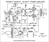
The ST-70 and the Mark III are effectively identical in terms of circuit design. Different tube types and component values, but the path is the same. Colored lines have audio signal on them

Blue is signal in from the jack. It gets to the grid of the pentode side of the 6AN8 (7199 in an ST-70) to be amplified. Not sure what the gain is here, probably 50x or something.
Output from the pentode plate to the triode grid. The triode is the phase inverter. No gain here, you actually get a slight loss of signal.
Output from the triode is on both plate and cathode. Plate is inverted phase, cathode is non-inverted phase. Both feed to 6550/KT88 grids (EL34 in the ST-70)
output tube plates feed to the transformer
secondary of the transformer to the speakers
 
Just a wee bit Gadget, the gain from either plate or cathode to ground is less than 1. But since this is balanced, I think it entirely appropriate to measure from plate to cathode, in which case the gain is nearly 2. Since the pentode's cathode is grounded, measuring its signal from ground to plate is appropriate, but it is ultimately the plate to cathode voltage that should be measured. When this approach is taken with a split load stage like these amps, the gain is indeed there.

Also, to Donstaff, note the indicated voltages by the shape of the sine waves; this represents their phase, and in case of the pentode input stage you'll note that it is inverted at the plate. Grid votlage increasing lets the tube conduct more current, and thus the voltage across the plate load increases. Since the upper end is tied to B+, the plate voltage drops as the grid increases.

Long ago I measured the gain of the 6AN8 pentode stage. In the two examples I had the gain was about 150.
cheers,
Douglas
 
Don, if the amp is of unknown origin, and at least 30 years since it may have last been turned on, then I'd strongly recommend that signal tracing is initially pushed to the back of the queue, and the focus is more to how one might approach an amp with unknown status (ie. it could have a fault that could take out other parts, or take you out, if you turn it on).

Different paths are taken by different people. Some will go straight for the bulb-limiter and turn it on. I go completely to the other end of the spectrum and quickly test all parts in a step by step manner, and appraise mains AC safety issues, and energise sections in a step by step manner, because I can do such tests as I have suitable equipment (eg. a variac and a megger) and experience. That ends up with basically a safe amp that has DC voltage levels around all of the circuitry, and before any signal is applied. That often also requires more than one set of valves, or other valve testing gear, to have confidence that valves don't have leaky grids, and can sit the anode voltage at a reasonable level so as to bias the PI stage appropriately, or balance the output stage cathode currents. So I would suggest that there can be a lot to do and learn before the amp even sees an oscillator on the input.
 
The 6AN8/7199 input stage pentode needs its plate voltage set carefully. The best way I have found to do this is by tweaking the resistor that drops to its g2. OE here is 1.5MOhm. Have not been able to tell any difference when eyeballing the output on a scope, save for two amps with identical input stages( by plate voltage ) clip at the same time/power out. This plate voltage should be at the triode section's B+/4.

But trobbins is entirely correct; get the amps running with fully functional power supplies( most likely to be interpreted as new caps in the B+ and bias, and replacement of the selenium diode that fires the bias ). At a minimum.
cheers,
Douglas
 
The 6AN8/7199 input stage pentode needs its plate voltage set carefully. The best way I have found to do this is by tweaking the resistor that drops to its g2. OE here is 1.5MOhm. Have not been able to tell any difference when eyeballing the output on a scope, save for two amps with identical input stages( by plate voltage ) clip at the same time/power out. This plate voltage should be at the triode section's B+/4.

But trobbins is entirely correct; get the amps running with fully functional power supplies( most likely to be interpreted as new caps in the B+ and bias, and replacement of the selenium diode that fires the bias ). At a minimum.
cheers,
Douglas
I use 1 meg Cermet Trimpots in place of the 1.5 meg screen resistors in my Stereo 70, one might try 820k mf resistors otherwise to get the splitter voltage distribution closer to ideal.
1118201801.jpg
 
Thanks for the advice and I will hold off on applying power and the signal oscilator. Would my safest my bet in light of my vast inexperience and lack of advanced equipment be to take the advice that peterh offered on Feb. 6 and start with a 50 ohm load resistor across the speaker terminals, then with the 6550 tubes removed, check the voltage between ground and pin 5? Still don't know if he meant pin 5 test point or pin 5 of the output tube socket. Could someone clearafy that?

Don
 
Thanks for the advice and I will hold off on applying power and the signal oscilator. Would my safest my bet in light of my vast inexperience and lack of advanced equipment be to take the advice that peterh offered on Feb. 6 and start with a 50 ohm load resistor across the speaker terminals, then with the 6550 tubes removed, check the voltage between ground and pin 5? Still don't know if he meant pin 5 test point or pin 5 of the output tube socket. Could someone clearafy that?

Don
Pin 5 on the output tube socket is connected to the grid. Here you should expect the bias voltage to show up,
between -30 to -45 volt between the pin5 and chassies, adjustable with the bias pot.
When this has been done, leave the pot in it's most negative position, this will ensure that when power tubes are mounted they will begin in the lowest current avoiding current surge before bias adustment.
 
The risk with removing output stage tubes, and then powering up, is that the filter caps and coupling caps may well be exposed to noticeably higher voltages than those caps are rated for. That can be exacerbated by having a modern-day higher mains AC voltage than the vintage amp was nominally set up for. The main filter caps may also need a soft start to allow reforming and lower the initial leakage current to a survivable level. It is not unheard of for a bad main filter cap to take out the power transformer and/or the rectifier tube. Likewise the rectifier tube could be gassy and start arcing and it is not unheard of for that to then take out the power transformer.
 
Back
Top Bottom