

You are using an out of date browser. It may not display this or other websites correctly.
You should upgrade or use an alternative browser.
You should upgrade or use an alternative browser.
Dynakit ST70
- Thread starter Tucker_515
- Start date

David_NC
Super Member
There are really very few electrolytic caps in an ST-70... a dozen or so. It doesn't take much more time to simply replace them vs test them. They are cheap and easy to replace. It seems that if one wants a reliable and good-sounding ST-70 that one should just go ahead and replace themBy this point, the newest can capacitor in an original ST-70 is at least 40 years old, and given that the average lifespan of an electrolytic capacitor is 10-20 years, they're all sure to be living on borrowed time by now. Also, not all capacitor checkers have the ability to test them at full rated voltage, which can affect how they test. At this point, it's better to be safe rather than sorry, especially since a failure of one or more sections could take out valuable components up to and including the power transformer.
With regard to the rest of the capacitors, the molded-paper capacitors are a known failure point, and should be replaced with modern film capacitors of the same or similar values. Modern film capacitors are far more reliable, and are fairly cheap unless you go for the fancy types, which I don't see as necessary. Mica and ceramic capacitors are fairly reliable, and should be left alone unless there is a reason to suspect them.
-Adam

This is probably the easiest tube amplifier to refurbish. I won't change out just one cap. For me it's why put in one non-matching cap when I can replace them all and have matching. Of course change the selenium rectifier and after 60 years just change the can. The only real deviation from stock on mine is upping the capacitance of the two electrolytics underneath and running 6U8 tubes with adapters. 7199's aren't very good or reliable tubes and I think it sounds better with the 6U8's. Most people lift traces because their soldering iron is set too low so they stay on the joint too long. I run my soldering iron at about 750 degrees. On and off quick. You want your ST-70 to run for a long time trouble free get rid of the old stuff. I look at it this way. If I had a classic muscle car with drum brakes I certainly wouldn't drive it that way. It would get disc brakes. Some upgrades are just common sense. I'm also partial to the yellow IC caps in tube gear.
Last edited:

Pio1980
AK Member
Three elyticaps, total, in the OEM configuration. The quad can hvps, and the two in the bias supply. The larger quad can replacement option highly recommended with the 40uF section first from the rectifier, the 80 after the choke, then the 30uF followed by the 20uF section. Same price and voltages as the lower capacity replacement.There are really very few electrolytic caps in an ST-70... a dozen or so. It doesn't take much more time to simply replace them vs test them. They are cheap and easy to replace. It seems that if one wants a reliable and good-sounding ST-70 that one should just go ahead and replace them
David_NC
Super Member
Good call on the soldering iron and lifting traces. I had that issue on a Pioneer receiver I was attempting to repair years ago. One pointer that a friend gave me is to match the soldering iron tip to the job. In this case, the pencil tip wasn't the best. A chisel tip worked much better for me when I was working on my Dynaco; I had zero issues with the traces on the old board.This is probably the easiest tube amplifier to refurbish. I won't change out just one cap. For me it's why put in one non-matching cap when I can replace them all and have matching. Of course change the selenium rectifier and after 60 years just change the can. The only real deviation from stock on mine is upping the capacitance of the two electrolytics underneath and running 6U8 tubes with adapters. 7199's aren't very good or reliable tubes and I think it sounds better with the 6U8's. Most people lift traces because their soldering iron is set too low so they stay on the joint too long. I run my soldering iron at about 750 degrees. On and off quick. You want your ST-70 to run for a long time trouble free get rid of the old stuff. I look at it this way. If I had a classic muscle car with drum brakes I certainly wouldn't drive it that way. It would get disc brakes. Some upgrades are just common sense. I'm also partial to the yellow IC caps in tube gear.
David_NC
Super Member
I replaced the six on the board along with the cap can (I used the upgraded one too) and the two underneath.Three elyticaps, total, in the OEM configuration. The quad can hvps, and the two in the bias supply. The larger quad can replacement option highly recommended with the 40uF section first from the rectifier, the 80 after the choke, then the 30uF followed by the 20uF section. Same price and voltages as the lower capacity replacement.
Pio1980
AK Member
OK, those on the board are not elyticaps, but good to replace for reliability regardless. If several of the resistors check out of tolerance, a populated replacement board with the 6GH8/6AN8/6U8 option can be considered a good plan.I replaced the six on the board along with the cap can (I used the upgraded one too) and the two underneath.
Tucker_515
New Member
Thank you guys so much for the information and suggestions. I haven't had time to further dive into it and take more pictures, but I will hopefully tomorrow post more. My Variac came today and I have a quick question about that. It has a 3 prong plug, so if I remove the ground prong, wouldn't it also act as an isolation transformer?
Today or tomorrow I want to order everything I need in one big bundle. I'm just going to replace the old caps and be done. I'll get all caps from DynakitParts.com. The factory can cap has values of 30, 20, 20, 20 I believe. They sell many different variations, any opinions? @Pio1980 suggested the 40, 80, 30, 20, but I don't want to change the sound.
For tubes, I'm going to get them from TubesandMore.com. I am planning on getting a quad of electroharmonix EL34s. Any other opinions? I also looked at the JJ's. What is the difference between apex matched and burned-in matched? For the 5AR4 I'm considering the Sovtek's. For the 7199s, I'm going to get the adaptors and run 6GH8's. I'm not looking for super expensive ones, but some that are decent enough to listen to for a while.
When I check the resistors, do I have to do them all out of circuit? Oh, and I want to replace the selenium rectifier, I'll probably just get the Bias Circuit Kit from DynakitParts.com that comes with everything. Any difference between Carbon Comp and Metal Film resistors?
Thanks everyone, Tucker.
Today or tomorrow I want to order everything I need in one big bundle. I'm just going to replace the old caps and be done. I'll get all caps from DynakitParts.com. The factory can cap has values of 30, 20, 20, 20 I believe. They sell many different variations, any opinions? @Pio1980 suggested the 40, 80, 30, 20, but I don't want to change the sound.
For tubes, I'm going to get them from TubesandMore.com. I am planning on getting a quad of electroharmonix EL34s. Any other opinions? I also looked at the JJ's. What is the difference between apex matched and burned-in matched? For the 5AR4 I'm considering the Sovtek's. For the 7199s, I'm going to get the adaptors and run 6GH8's. I'm not looking for super expensive ones, but some that are decent enough to listen to for a while.
When I check the resistors, do I have to do them all out of circuit? Oh, and I want to replace the selenium rectifier, I'll probably just get the Bias Circuit Kit from DynakitParts.com that comes with everything. Any difference between Carbon Comp and Metal Film resistors?
Thanks everyone, Tucker.

That's not how variacs (and isolation transformers) work, generally. Isolation transformers, as the name suggests, are 1:1 transformers which isolate the device plugged into them from the actual line wires. Variacs, generally, are referred to as "autotransformers" or "variable transformers"; one side is still connected to the incoming line. They do make actual isolating variacs, but you have to specifically get one (not cheap), or add an outboard isolation transformer ahead of a regular variac. Here's a crude schematic for a non-isolating variac-based device tester I built:Thank you guys so much for the information and suggestions. I haven't had time to further dive into it and take more pictures, but I will hopefully tomorrow post more. My Variac came today and I have a quick question about that. It has a 3 prong plug, so if I remove the ground prong, wouldn't it also act as an isolation transformer?
Today or tomorrow I want to order everything I need in one big bundle. I'm just going to replace the old caps and be done. I'll get all caps from DynakitParts.com. The factory can cap has values of 30, 20, 20, 20 I believe. They sell many different variations, any opinions? @Pio1980 suggested the 40, 80, 30, 20, but I don't want to change the sound.
For tubes, I'm going to get them from TubesandMore.com. I am planning on getting a quad of electroharmonix EL34s. Any other opinions? I also looked at the JJ's. What is the difference between apex matched and burned-in matched? For the 5AR4 I'm considering the Sovtek's. For the 7199s, I'm going to get the adaptors and run 6GH8's. I'm not looking for super expensive ones, but some that are decent enough to listen to for a while.
When I check the resistors, do I have to do them all out of circuit? Oh, and I want to replace the selenium rectifier, I'll probably just get the Bias Circuit Kit from DynakitParts.com that comes with everything. Any difference between Carbon Comp and Metal Film resistors?
Thanks everyone, Tucker.
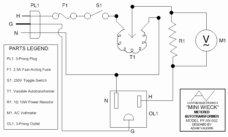
In any case, an isolation transformer is not absolutely necessary for this application, as the power transformer in the ST-70 provides its own sort of isolation from the line. By the way, do NOT remove the ground lead of any power cord; doing so is a good way to lead to getting shocked anyway if something goes wrong. That third prong is put there for a reason.
I'm planning to replace the can capacitor in my ST-70 with the stock 30/20/20/20@525V values. The uprated can Pio mentioned isn't a bad choice; however, you need to make sure that the first capacitor value after the rectifier tube is the 30 or 40µF section, rather than the 80µF one which is the first mentioned on the can. Tube rectifiers don't like to see too large a value ahead of them, and the max limit of the 5AR4 is 40µF.
Electro-Harmonix EL34s are decent tubes, as are the 'big bottle' 6CA7s they also offer. For 7199s, I wouldn't replace them unless they're proven to be bad. The same goes for the Matsushita 5AR4, since it's likely better than any of the modern production 5AR4s being made today. The Realistic-branded one in my ST-70 has been there since I bought it in 2001, and it shows no signs of weakening.
Metal film resistors are better technologically than carbon comp ones in pretty much every way, being far less prone to drifting in value. With regards to checking resistor values, the best way to do so is out-of-circuit. However, testing a resistor in-circuit will at least give you a basic idea of its current condition. Resistors connected in parallel lowers their value; if you measure a resistor and it tests lower than its marked value, it's probably fine. If it tests higher than its rated value, however, it's likely drifted way high. High value resistors (470kΩ or larger) seem to drift more often than smaller value ones, though those can drift as well. Hope this helps.
-Adam

Tucker_515
New Member
Alrighty, I have the Bias Circuit Kit in my 'cart' along with the 30, 20, 20, 20 capacitor can for a straight up replacement. I also have a parts kit because I am missing one screw, but I will probably just track one down at a hardware store because the kit is 10 bucks. I have also heard the RCA jacks can be temperamental, should I order the upgraded ones right away? Or just leave the factory ones in? I could also order original replacements for cheaper.
Regarding the tubes I'll be buying, they are not to replace the originals, they are to be used temporarily until I know the unit is 100%, which I figured would be a month or two so I want ones that still sound pretty good.
Thanks, Tucker
Regarding the tubes I'll be buying, they are not to replace the originals, they are to be used temporarily until I know the unit is 100%, which I figured would be a month or two so I want ones that still sound pretty good.
Thanks, Tucker

The Nesstone EL34 quad is about $40 and pretty good sounding as well. I would assume the other tubes are ok but you could pick up a Sovtek rectifier for around $25.
Projects like this can nickel and dime you to death so I’d recommend the hardware store.
Projects like this can nickel and dime you to death so I’d recommend the hardware store.
Don't forget about the replacements for the molded-paper capacitors on the driver board! Four 0.1µF@400V and two 0.047µF@400V. It's OK to use higher voltage rated capacitors, of course.Alrighty, I have the Bias Circuit Kit in my 'cart' along with the 30, 20, 20, 20 capacitor can for a straight up replacement. I also have a parts kit because I am missing one screw, but I will probably just track one down at a hardware store because the kit is 10 bucks. I have also heard the RCA jacks can be temperamental, should I order the upgraded ones right away? Or just leave the factory ones in? I could also order original replacements for cheaper.
Regarding the tubes I'll be buying, they are not to replace the originals, they are to be used temporarily until I know the unit is 100%, which I figured would be a month or two so I want ones that still sound pretty good.
Thanks, Tucker
The main problem most folks have with the RCA jacks in the ST-70 is that they're closer together than is generally seen on modern equipment. This tends to prevent fancy modern cables with big plugs from fitting side-by-side in the jacks, though I've managed fairly well with the original jacks on my ST-70. I will say that I ran into connection issues with the RCA jacks on my Mark III monoblocks and my ST-35, both of which used a different style of jack. I replaced them with modern chassis-mount single RCA jacks.
When I got my ST-70, the EL34s it came with were a mismatched mess; three of them were Japanese-made (may have been branded Dynaco, though I think the markings had faded) with a seam across the top, plus a Mullard of some sort. All three of the originals were extremely weak; the pair with two of them installed would barely bias to 0.5V, while the mismatched pair *could* be biased to 1.56V, though the Mullard(!) would develop a red spot on the plate when I did. I ordered a matched quad of JJ/Tesla E34Ls, which were considered pretty good at the time (2001), and they improved matters dramatically. However, one of the E34L pairs went weak a few years later, so I replaced all four with Electro-Harmonix EL34s, which I used until a couple of years ago, and they still test/bias well after 10+ years of use.
-Adam
Last edited:

JohnT123
Super Member
FWIW, a couple years ago I sat down with all the Russian variants of the GZ34. I had the Sovtek, Tung Sol, Mullard and Genelex. I tested each in circuit and found the voltage drop, sag effects and B+ to be virtually identical. The internal elements also looked to be identical. The only difference I could guarantee was the screening and base configuration.
How is it that so many people feel so strongly that there is a measurable difference in quality?
How is it that so many people feel so strongly that there is a measurable difference in quality?

I hope my esteemed colleagues will forgive me if I beg to differ on a couple of points. I'd avoid Nesstone or any other Chinese-made octal base tubes. My concern is that every Chinese octal base tube I’ve owned, and most I’ve seen images of online, have pins that are splayed-out and/or have bulbous solder on the ends of their pins.
Pin splaying and/or bulbous solder tends to deform tube socket contacts, and this can lead to problems not the least of which is tube red-plating when you swap in a different set of tubes having straight pins. Red-plating destroys tubes pretty quickly. Of course, a way around this would be to put a good deal of time and effort into resoldering and straightening the pins (ugh), or be very diligent about cleaning and retensioning the socket contacts before swapping-in a different set of tubes.
While in this day and age I can not recommend buying anything made in China if one can avoid it, but the last couple of sets of Psvane EL34B's I have used have been excellent, no crookedness, no crappy soldering joints on the pins, very nice tubes that sound good in my Sound Valves VTA-70i, equally as good as the JJ KT-77s...
I also recommend buying matched quads as if you swap tubes around you don't have to worry about which tube socket you place them back into after swaps...it makes biasing a lot simpler, IMNSHO.
Tucker_515
New Member
I'll check out the other rectifier tubes and their prices. I'm already at $200 with tubes and caps, which isn't a problem, but if I can save some money, that would be great because I still need to go through my PAS-2!
As for the PC board caps, I was just going to order the 5% metalized polypropylene caps from dynakitparts.com. The sizes are about the same as the factory ones and their voltage ratings are much higher.
I'll check my RCA jacks out to make sure they aren't loose or anything. If they are I'll just order the factory ones because they are cheap and find some narrower RCA plugs to go into them.
Thanks, Tucker
As for the PC board caps, I was just going to order the 5% metalized polypropylene caps from dynakitparts.com. The sizes are about the same as the factory ones and their voltage ratings are much higher.
I'll check my RCA jacks out to make sure they aren't loose or anything. If they are I'll just order the factory ones because they are cheap and find some narrower RCA plugs to go into them.
Thanks, Tucker

Lavane
Lunatic Member
I've bought a few different cheap octal Chinese tubes from Nesstone.I hope my esteemed colleagues will forgive me if I beg to differ on a couple of points. I'd avoid Nesstone or any other Chinese-made octal base tubes. My concern is that every Chinese octal base tube I’ve owned, and most I’ve seen images of online, have pins that are splayed-out and/or have bulbous solder on the ends of their pins.
Pin splaying and/or bulbous solder tends to deform tube socket contacts, and this can lead to problems not the least of which is tube red-plating when you swap in a different set of tubes having straight pins. Red-plating destroys tubes pretty quickly. Of course, a way around this would be to put a good deal of time and effort into resoldering and straightening the pins (ugh), or be very diligent about cleaning and retensioning the socket contacts before swapping-in a different set of tubes.
I’d also not exceed the voltage rating of the coupling capacitors on the PC board because parts with a higher voltage rating will be physically larger, take up more real estate on the PC board and may also sit closer to the tubes, which means greater heat stress on the part. It might not end up being necessary to replace these capacitors, anyway.
IMO, I don’t think of the original RCA jacks as temperamental. As Adam mentioned, their spacing is too close for a lot of present-day interconnects [the likes of which didn’t exist years ago when the Dynaco was designed]. The other problem is that they can corrode due to sheer age. If you get exact replacement input jacks, you’d have to find interconnects having thinner RCA plugs, otherwise you might need to force them, to some degree, into the jacks. Or, just get the wider-spaced jacks https://www.dynakitparts.com/shop/rca-jacks-st-70-upgrade/
A fine idea, and all the more reason to try to get them burned-in with all four matched. You may like them well enough that you’ll want to listen to them for even longer. I mentioned the Tung Sol 5AR4 and the Gold Lion GZ34 because they are more robust and would likely last longer than the Sovtek 5AR4.
I bought them to use for testing in old and newly built amps. The bases aren't secured very well and the soldering on the pins wasn't great. Fine for testing, but I wouldn't run them long term. Not all of the tubes he sells are junk though. Just stay away from the cheap Chinses offerings.
I wouldn’t run those tubes long term either. No, the pins are not the best.
Those caps from Dynakit are good, and good sounding.
Those caps from Dynakit are good, and good sounding.
I think he's referring to the metallized polypropylene capacitors they sell, i.e. the kind meant to be used on the driver board. In the old days, capacitor values were more often to be found as 100/200/400/600V, while nowadays you're more likely to find those capacitors in 630V thanks to improvements in materials and whatnot. I don't think that using a solid-state rectifier would affect the capacitors on the driver board too much, in any case.I suspect the reason why the voltage rating is higher is in case someone uses a solid-state rectifier replacement for the rectifier tube, which will result in higher voltages on the parts in the amp. This wasn't an issue when the Stereo 70 was originally designed and is not necessary as long as a 5AR4/GZ34 is in use. The size being about the same as the originals doesn't always happen with a higher voltage rating. Kind of makes me wonder what's different about how they are wound. They're probably fine, though.
-Adam