• The move to the new server is done. There are some software and database maintenance updates in process. This has us passing the hat around to help out. We appreciate any donations. Seriously, even a dollar helps. The payment page may be found here - https://www.audiokarma.org/support.html

EL84 SEP amplifier

atmasphere

Active Member
I've been having fun with EL84s recently, which started with a refurbishment of a Dynaco ST35.

I'm convinced its power level and the ease at which it can be driven make it one of the best sounding pentodes made.

After refurbishing the ST35, my next project was a Nobles Manufacturing NS-130 which might be the most elegant EL84 based amp every built. They were made in St. Paul MN during the late 1950s and early 1960s and are quite rare.

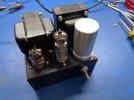
Online I saw people were messing with the RCA RS199 which is a stereo console SE power amp. Its rare and if I found one I'd be tempted to strip it to the nuts and bolts since I like things to look nice. That convinced me I might as well design one from scratch. I'm interested to see if it can compete against a 2A3 based SET.

This project is a pair of monoblocks, each making about 3.5 Watts. The power transformer is the Hammond 269EX. The output is the Edcor GXSE10-6-5K. which has an ultralinear connection.

My plan is as compact as possible. I might have to make two versions as it would be nice to have a balanced input using a differential amplifier which would also be the driver for the power tube. But right now the circuit I'm planning uses the 12AT7 sections in parallel to get as much bandwidth and Voltage swing as I can. I plan to play with feedback but will mix it on the grid of the input tube to reduce distortion, rather than the traditional means of using the cathode. That will help keep harmonic generation due to feedback to a minimum.
 
Register to hide this ad
EL84SEP.jpg
This is the proposed layout. I'm trying to keep it as compact as possible which is part of why I'm using a can electrolytic as it saves space below, which will have a choke for the power supply. Before I can build it up though, the chassis (Hammond aluminum, special ordered thru CE Distribution to get that size) has to get painted along with the end shells for the output transformer so everything looks like its supposed to be there. I plan a toggle switch and old school pilot lamp on the front panel (as shown). The rear will get an RCA jack (probabaly Cardas), speaker terminals in the form of a 5-way binding post, fuseholder and power cord strain-relieved.
 
If you really want to save space, use a small LED pilot lamp.
Ive used them on several projects. They're small, cheap, panel mount, and come in a bag of 5.
 

Attachments

  • 20250626_134540.jpg
    20250626_134540.jpg
    162.5 KB · Views: 40
  • 20241203_125728.jpg
    20241203_125728.jpg
    69.5 KB · Views: 40
  • 20230822_160002.jpg
    20230822_160002.jpg
    133.7 KB · Views: 40
If you really want to save space, use a small LED pilot lamp.
Ive used them on several projects. They're small, cheap, panel mount, and come in a bag of 5.
Since I'm already using a can filter cap, in keeping with the vintage look I'm going with a real pilot lamp (type 47) and a full size toggle switch.
 
My plan is as compact as possible.

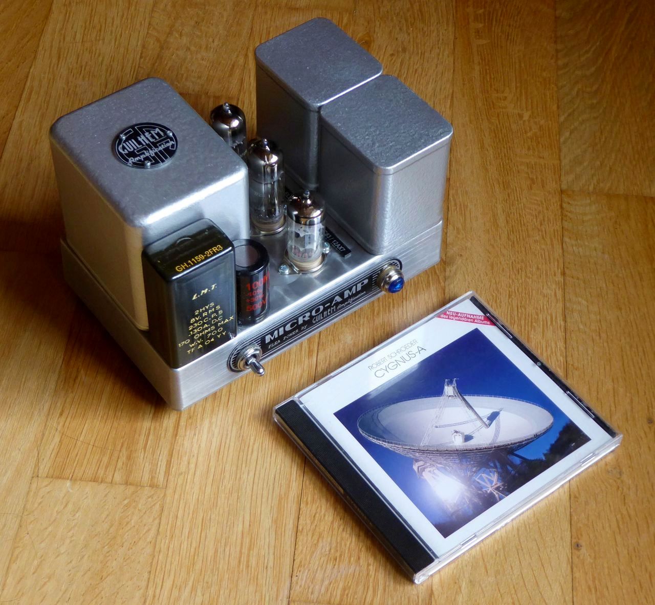
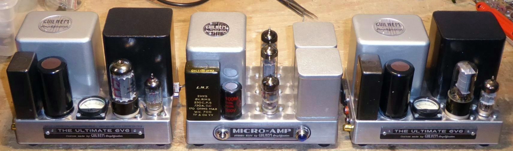
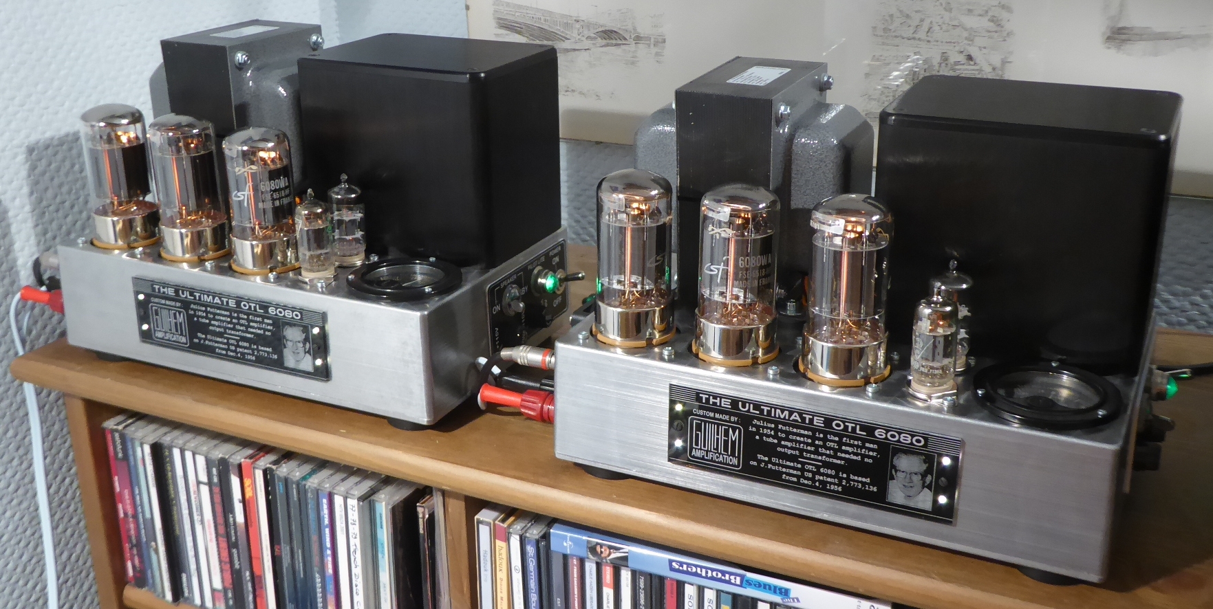
Aha @atmasphere ! It is the first time that I see a serious competitor to my Micro-Amp...

AV0BQb-P1180893.jpg


BV0BQb-P1180867.jpg


AV0BQb-P1180859.jpg


56GvQb-MICRO-AMP-cablage-fini-18-07-2023.jpg


For me, the challenge was to find the convenient parts for compacity ! ;)

T
 
How are you isolating the source impedance from the feedback? Thats usually been my issue with bringing feedback into the grid. It ends up dividing the feedback signal through the grid to ground resistor in parallel with the source impedance. Change the source, change the source impedance, change the feedback level.

If its a mono amp and the front end tube is a twin triode you could use half of it as a cathode follower to have a predictable source impedance though.
 
Hi All,

Been using this amplifier to drive the tops of my Dad's 1963 Khorns in the shop system, I call it "Lil ****" . It came out of a 1959 Ampex 1270 Suitcase Reel to Reel. It uses:

2-6AQ5,
EZ81
12AX7

I think it's 3.5 watts. Does a nice job and is fun to play with. I have it paired with a very early McIntosh C20 Preamp.. I added the banana plugs and longer ac cord, brass cone footers. I picked it up from buddy in Chicago. The pot is suppose to be for a little treble adjustment. I hear no difference when I turn it one way or another.
 

Attachments

  • 20251029_102029.jpg
    20251029_102029.jpg
    129.8 KB · Views: 38
  • 20251029_102015.jpg
    20251029_102015.jpg
    85.5 KB · Views: 37
  • 20251029_102024.jpg
    20251029_102024.jpg
    138.8 KB · Views: 38
  • Resized(1747766241939)_Resized_20250520_133713(1).jpeg
    Resized(1747766241939)_Resized_20250520_133713(1).jpeg
    123.9 KB · Views: 37
  • Resized_Screenshot_20250521_202553_Photos(1).jpeg
    Resized_Screenshot_20250521_202553_Photos(1).jpeg
    92.7 KB · Views: 38
Hi All,

Been using this amplifier to drive the tops of my Dad's 1963 Khorns in the shop system, I call it "Lil ****" . It came out of a 1959 Ampex 1270 Suitcase Reel to Reel. It uses:

2-6AQ5,
EZ81
12AX7

I think it's 3.5 watts. Does a nice job and is fun to play with. I have it paired with a very early McIntosh C20 Preamp.. I added the banana plugs and longer ac cord, brass cone footers. I picked it up from buddy in Chicago. The pot is suppose to be for a little treble adjustment. I hear no difference when I turn it one way or another.
6AQ5's are nice sounding little tubes.
 
How are you isolating the source impedance from the feedback? Thats usually been my issue with bringing feedback into the grid. It ends up dividing the feedback signal through the grid to ground resistor in parallel with the source impedance. Change the source, change the source impedance, change the feedback level.
You do it in the same manner as an opamp. There is a resistance in series with the signal and you can use that as a stopping resistor right at the grid of the tube. You run the feedback to the same spot. It won't work right without that series input resistance.

This requires that the output of the amp is inverted WRT the input. That's easy to do if you have an output transformer. We've been using this technique in our OTLs, which are fully differential and balanced for decades on now.
Cute. I like it. Now you need a compact preamp to go with it :thumbsup:
Maybe something really simple with a single tone control.
I've been experiementing using an EF86 in ultra-linear mode. A preamp using a 6AU6 in ultra linear mode would be quite compact!

Currently the amp is being built with the EF86 rather than the 12AT7. The output section is ultralinear too. I plan global feedback too and right now am leaning towards taking it off the primary side of the OPT.
Aha @atmasphere ! It is the first time that I see a serious competitor to my Micro-Amp...

For me, the challenge was to find the convenient parts for compacity ! ;)

T
Lovely chassis work! Did you have that machined?
 
Still just not a fan of external connections influencing the internal operation of the amp. Feedback is still divided by the source output impedance plus the resistor in parallel with the grid to ground. To me this is a perfect use for a buffer stage to isolate things.
 
Lovely chassis work! Did you have that machined?

Thanks @atmasphere !

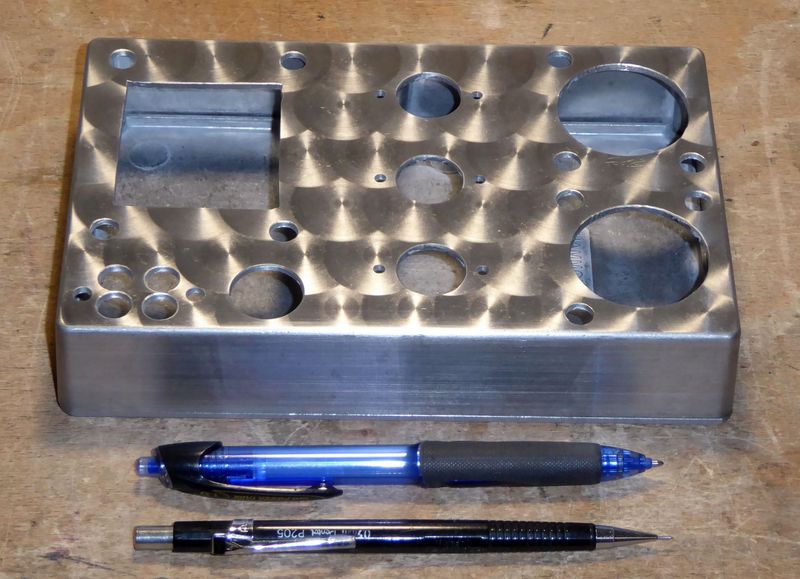
Oh, no ! it is simply Hammond chassis N° 1590DD, on which I did engine turning (upper face) and brushing (lateral faces), before cutting the openings :

o55gQb-P1180310.jpg


At first, like for your little model, it was intended to operate two EL84/6BQ5, but the power required by those tubes was a bit high for the power transformer, so I ended to shift for two EL85/6BN5, which is the Noval 9-pins version of the Rimlock 8-pins EL42, and is similar to the Miniature 7-pins EL95/6DL5.

---> How did you built your chassis ? I suppose that you have the toolings to work sheet metal, or rely on a subcontractor ? Can you give me the dimensiosn ?

Here's the schematic of my Micro-Amp - it's a modest one-watter per channel :

BV0BQb-MICRO-AMP-EL85-version-SCHEMATIC-03-08-23-reduced.jpg


I plan to shift from a 6L6 on my next little mono-blocks project (as pictured in my previous post) to an EL84 instead.

---> Maybe I'm missing something, but why / where would you use a feedback resistor at the grid ? I mean : what's the advantage - or the requirement ?

T
 
Still just not a fan of external connections influencing the internal operation of the amp. Feedback is still divided by the source output impedance plus the resistor in parallel with the grid to ground. To me this is a perfect use for a buffer stage to isolate things.
I've used this technique quite a lot. The external source impedance affects the feedback less than you suggest. The feedback resistor itself tends to be a rather high value on account of the high impedance of the grid so that ratio dominates the behavior of the feedback loop.

Thanks @atmasphere !

Oh, no ! it is simply Hammond chassis N° 1590DD, on which I did engine turning (upper face) and brushing (lateral faces), before cutting the openings :

o55gQb-P1180310.jpg


At first, like for your little model, it was intended to operate two EL84/6BQ5, but the power required by those tubes was a bit high for the power transformer, so I ended to shift for two EL85/6BN5, which is the Noval 9-pins version of the Rimlock 8-pins EL42, and is similar to the Miniature 7-pins EL95/6DL5.

---> How did you built your chassis ? I suppose that you have the toolings to work sheet metal, or rely on a subcontractor ? Can you give me the dimensiosn ?

Here's the schematic of my Micro-Amp - it's a modest one-watter per channel :

BV0BQb-MICRO-AMP-EL85-version-SCHEMATIC-03-08-23-reduced.jpg


I plan to shift from a 6L6 on my next little mono-blocks project (as pictured in my previous post) to an EL84 instead.

---> Maybe I'm missing something, but why / where would you use a feedback resistor at the grid ? I mean : what's the advantage - or the requirement ?

T
Using a feedback resistor in this manner prevents the distortion of the input tube from modifying the feedback signal while its being mixed with the audio. This results in less higher ordered harmonic distortion and less IMD.

Like you, I'm simply using a Hammond chassis. Clearly I didn't have the vision you did so I didn't see the value of working with their cast stuff. I really like the turned finish you got! Did you anodize it after that (not sure cast aluminum can be anodized; some alloys just turn black)?

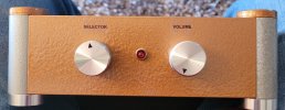
I also built an amp using the EL95. This one has a custom built chassis with welded and ground corners so I could get it polished and chromed, although this example isn't built that way.
GemWithChrome.jpg
This amp is class A, push pull, makes 5 Watt/channel, has two inputs and a volume control. Its fully differential so no dedicated phase splitter circuit.
 
Now that's kuel... AND it even has a genuine Mark Levinson ML knob. That would be very happy in my shop Ralph! Driving the khorns.

Bob
 
I really like the turned finish you got! Did you anodize it after that (not sure cast aluminum can be anodized; some alloys just turn black)?

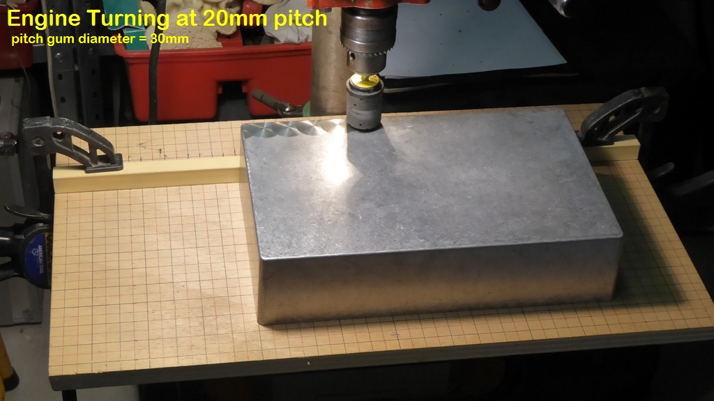
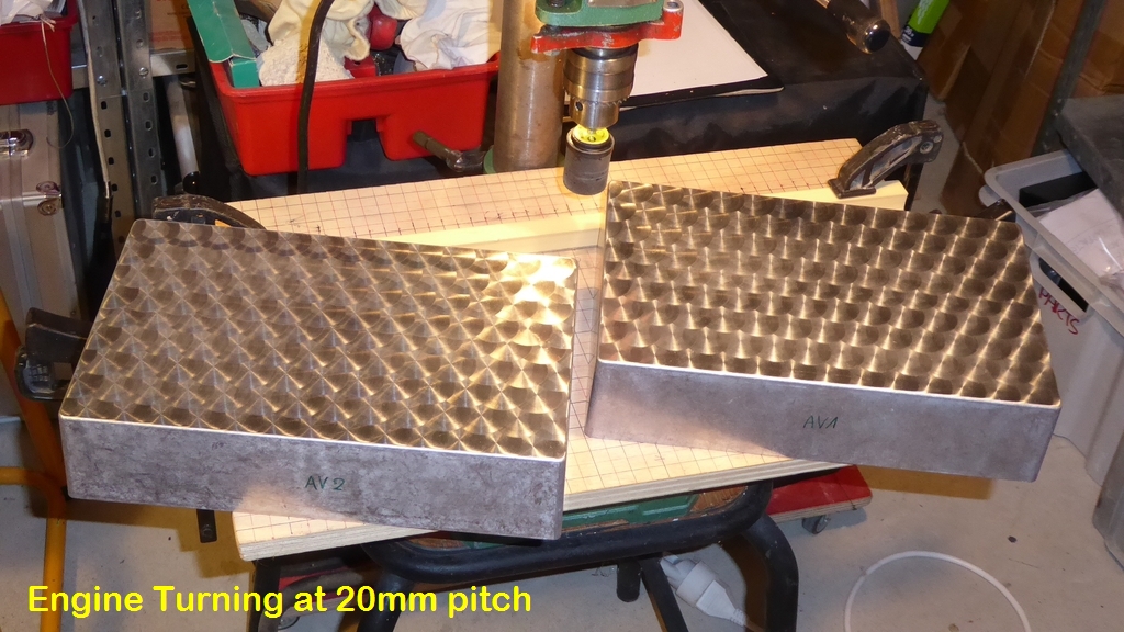
I use a special drill-press rubber find locally for this - we call it bouchonnage in French :

j2cOJb-P1100204.jpg


k2cOJb-P1100212.jpg


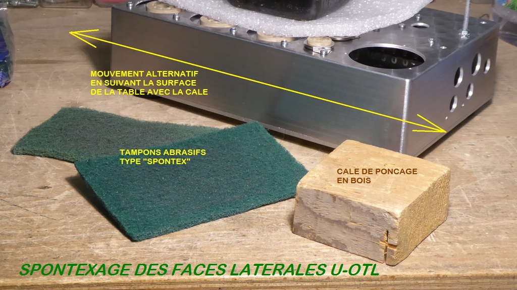
For the sides, I use a woodbock and slightly abrasive cloth called "Spontex" :

Y0cSJb-P1100239.jpg


At the start, I simply degrease with Acetone and clean with hot soaped water the box, and once the work done, I redo the same. No other surface treatments. The alloy used by Hammond for their 1590 die-cast boxes is fine, because it doesn't tarnish with time.

gaZXJb-P1100324.jpg


T
 
Now that's kuel... AND it even has a genuine Mark Levinson ML knob. That would be very happy in my shop Ralph! Driving the khorns.

Bob
It drives them very well! Small PP amps like this really take SETs of similar power to task! So much more bandwidth and much lower distortion, so more of the amplifier's power is actually usable.

The SEP is alive. This is the circuit I'm working with at present:

SEPSchem.jpg

You can see the power supply is very simple, yet the circuit is free of hum. The screen tap is doing double duty. There's some degenerative feedback in this circuit, along with the ultra-linear operation of both stages. I'm not having trouble with gain so far, but if I'm going to use loop feedback I'll probably start with bypassing the cathodes.

I threw this together without doing any math; its obvious the cathode resistor of the Voltage amplifier needs adjustment. The circuit might change quite a lot as I sort out how to get more Voltage swing out of the first stage while still using the screen tap to feed it. The attraction is the simplicity of the power supply.
 
Back
Top Bottom