


You are using an out of date browser. It may not display this or other websites correctly.
You should upgrade or use an alternative browser.
You should upgrade or use an alternative browser.
EL84 SEP amplifier
- Thread starter atmasphere
- Start date

atmasphere
Active Member
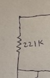
It functions as feedback for the output and as a plate load for the EF86. Totally experimental in that I've not seen a circuit like that before. But it seems to work. Not put it on the bench yet to see how bad the distortion is, but it sounds pretty good anyway.
tubelectron
Super Member
It functions as feedback for the output and as a plate load for the EF86. Totally experimental in that I've not seen a circuit like that before. But it seems to work. Not put it on the bench yet to see how bad the distortion is, but it sounds pretty good anyway.
I see... this FB/load resistor may also have an additional positive influence about the HV hum, by injecting some reverse phase hum to the preamp section, when taken at the screen tap ?
Let us know !


I want to say @PakProtector has talked about using the UL tap as the supply for the front end voltage amp before. Its the E-Linear circuit.
 audioxpress.com
A Single-Ended “E-Linear” Power Amplifier
This simple single-ended amp project by Pete Millett is a great performer and a very well documented project that was immediately adopted by many DIY'er's. The amplifier achieves good power output and low distortion by employing “E-linear” feedback in the output stage. This article was published...
tubelectron
Super Member
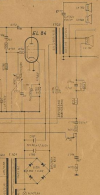
Yes. a similar disposition has been used in the 50s at least by Blaupunkt, where a section of the output transformer (T702) is used in reverse phase as a choke :
T
T
Thats a somewhat different configuration, its largely a choke but also partly a hum bucker. Any hum at the screen is out of phase with the hum at the plate so it cancels if the balance is right. A lot of basic table radios used that setup, but it turns up once in a while in low end audio amps too. Hot chassis stuff especially, they had half wave rectification and 60hz ripple is harder to filter than 120hz.
atmasphere
Active Member
I've been continuing to tamper.
The schematic:
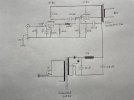
I was wrong about being hum free... The choke took care of that, but I lost a bit of B+ Voltage; I went to the 115V tap which helped.. I needed some gain so bypassed the cathodes, using the Ultrapath for the output.
Here's the rear panel:
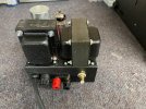
I'm getting about 5% THD at full output but due to the low B+ Voltage that's about 2.5Watts. I really should have a bigger power supply transformer. Its not shown on the schematic but the chassis is grounded through the ground of the power cord. That is why there's that 100 Ohm resistor to 'earth ground' seen in the schematic. The audio ground floats with respect to chassis at 0 Volts via that resistor. This prevents ground loops.
The schematic:
I was wrong about being hum free... The choke took care of that, but I lost a bit of B+ Voltage; I went to the 115V tap which helped.. I needed some gain so bypassed the cathodes, using the Ultrapath for the output.
Here's the rear panel:
I'm getting about 5% THD at full output but due to the low B+ Voltage that's about 2.5Watts. I really should have a bigger power supply transformer. Its not shown on the schematic but the chassis is grounded through the ground of the power cord. That is why there's that 100 Ohm resistor to 'earth ground' seen in the schematic. The audio ground floats with respect to chassis at 0 Volts via that resistor. This prevents ground loops.
atmasphere
Active Member
Both channels are now running and we've been playing them in the shop system for about a day.
tubelectron
Super Member
That's good, @atmasphere  , but : what do you mean by "Ultrapath" ?
This ?

Or that ?
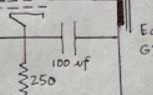
What B+ voltage do you have here ? It is probably "forced" by the 250R cathode resistor, to reduce plate current of the EL84, if the power of the PT is small ? I'd say circa 220-230VDC ?
Edit : OK - I saw that the 269EX is a 2x190V @71mA. Enough current, but a bit short in volts... So what are your Vp, Vs and Vk on the EL84 here ?
T
, but : what do you mean by "Ultrapath" ?This ?
Or that ?
What B+ voltage do you have here ? It is probably "forced" by the 250R cathode resistor, to reduce plate current of the EL84, if the power of the PT is small ? I'd say circa 220-230VDC ?
Edit : OK - I saw that the 269EX is a 2x190V @71mA. Enough current, but a bit short in volts... So what are your Vp, Vs and Vk on the EL84 here ?
T
Last edited:
an ultrapath cap runs from cathode to B+ instead of cathode to ground.
atmasphere
Active Member
Actual plate Voltage is 266V. The screen runs slightly higher. About 9.4V on the cathode. The 250Ohm resistor was all I had laying around that was in the ball park.What B+ voltage do you have here ? It is probably "forced" by the 250R cathode resistor, to reduce plate current of the EL84, if the power of the PT is small ? I'd say circa 220-230VDC ?
Edit : OK - I saw that the 269EX is a 2x190V @71mA. Enough current, but a bit short in volts... So what are your Vp, Vs and Vk on the EL84 here ?
T
tubelectron
Super Member
an ultrapath cap runs from cathode to B+ instead of cathode to ground.
Ah, OK - thanks for the link @gadget73 !
Reading the article, I must confess that I did not understood the significant advantages to use the Ultrapath instead the conventional Cathode Bias circuit...
A possible advantage would be with a direct-heated Cathode Bias operation tube. At the instant of the start, the cathode will be highly overbiased, instead of shorted to GND through the decoupling capacitor. It would protect the tube against the inrush extra-current flowing into the tube, absorbed by the charge of the classic cathode to GND capacitor circuit, notably if this one has a high value.
Well, it a supposition that must be verified !
Actual plate Voltage is 266V. The screen runs slightly higher. About 9.4V on the cathode. The 250Ohm resistor was all I had laying around that was in the ball park.
9.4V/250R = 38mA cathode current. (266-9.4)x0.038=9.8W total dissipation at idle. That's very correct, considering the parts you had on hand...

Ultrapath was simply a way to bypass the cathode resistor without having to use a large capacitor (across the cathode resistor) which were very large and expensive in the early 20th century.an ultrapath cap runs from cathode to B+ instead of cathode to ground.
As far as sonics, its like everything in audio where you are going to have mixed opinions about it.
Not really sure it would have been cheaper. The value is the value, but tying to B+ it also needs to be higher voltage which would tend to be more expensive. A 20 microfarad to ground has slightly lower impedance than a 20 microfarad to B+ since that would also be in series with the B+ to ground caps.
I've honestly never seen an old piece of gear with a cap from cathode to B+. I've seen grounded cathodes and back bias though. That would allow for a cheaper cap
I've honestly never seen an old piece of gear with a cap from cathode to B+. I've seen grounded cathodes and back bias though. That would allow for a cheaper cap
atmasphere
Active Member
IIRC, a friend of mine, Jack Elliano, invented the Ultrapath concept.Ultrapath was simply a way to bypass the cathode resistor without having to use a large capacitor (across the cathode resistor) which were very large and expensive in the early 20th century.
Invented or popularized?IIRC, a friend of mine, Jack Elliano, invented the Ultrapath concept.
Taken out of context:
Straight forward circuit, a separate choke in each channel which allows the use of a common supply with minimal interaction between the channels. The driver stage B+ is derived from the same supply via it's own RC filter segment. In a more elaborate implementation this could be upgraded to LC, but since we are on a moderate budget, let's stick with RC here. But wait, there is one unusual aspect which is not commonly seen: The capacitors from B+ to cathode in both output and driver stage. This is the so called 'ultrapath' concept. The origins of this approach go back to the engineers from Western Electric. Lynn Olson covered this on his website in an article Western Electric - Rosetta Stone for Triodes. As far as I'm aware the first person to mentioned this approach again in 'modern' times and who re-introduced it to vacuum tube audio is Jack Elliano of Electra Print. He is also the one who named it 'ultrapath' in an article in the magazine Vacuum Tube Valley.

 vinylsavor.blogspot.com
Straight forward circuit, a separate choke in each channel which allows the use of a common supply with minimal interaction between the channels. The driver stage B+ is derived from the same supply via it's own RC filter segment. In a more elaborate implementation this could be upgraded to LC, but since we are on a moderate budget, let's stick with RC here. But wait, there is one unusual aspect which is not commonly seen: The capacitors from B+ to cathode in both output and driver stage. This is the so called 'ultrapath' concept. The origins of this approach go back to the engineers from Western Electric. Lynn Olson covered this on his website in an article Western Electric - Rosetta Stone for Triodes. As far as I'm aware the first person to mentioned this approach again in 'modern' times and who re-introduced it to vacuum tube audio is Jack Elliano of Electra Print. He is also the one who named it 'ultrapath' in an article in the magazine Vacuum Tube Valley.
Single Ended Amplifier Concept, Part 1
Hi! In the poll most visitors voted for single ended amplifiers. Most of them for a low budget amp, but many also for a cost no object SE ...
vinylsavor.blogspot.com
atmasphere
Active Member
Thanks!
tubelectron
Super Member
OK, I see... I re-read all the articles that you linked - Thanks you Guys !
This paragraph (except from the article https://www.dmitrynizh.com/Ultrapath.htm ) pretty sums it up well :

IMHO, the advantage of the mentioned shortness in the power signal path can be solved quite easily by a compact and adequate wiring, and a logical, short GND bus, still using the conventional by-passed Cathode Bias circuit.
Moreover, you don't have to care with that extra-sensivity to HV PSU ripple. Plus you can use large by-pass capacitor values, as available today, since the required voltage is much lower :
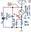
But it's me, OK ?
This paragraph (except from the article https://www.dmitrynizh.com/Ultrapath.htm ) pretty sums it up well :
IMHO, the advantage of the mentioned shortness in the power signal path can be solved quite easily by a compact and adequate wiring, and a logical, short GND bus, still using the conventional by-passed Cathode Bias circuit.
Moreover, you don't have to care with that extra-sensivity to HV PSU ripple. Plus you can use large by-pass capacitor values, as available today, since the required voltage is much lower :
But it's me, OK ?
atmasphere
Active Member
I gave up on the idea of using the OPT to supply any B+ to the EL86 so the current iteration looks a lot more conventional. I retained the UL idea for the EL86.

Full power seems to be 3 Watts.
The next step is feedback, including the output transformer secondary since I'm getting more gain than I need. By grounding one side of the OPT secondary and placing a 27K resistor between the OPT and the grid of the EL86 I get about 14dB of feedback, which sets the gain in a much more usable level.
There's a bit of ringing; I don't have the right values on hand to shut it down. 47pF helps but clearly isn't enough. I suspect 100pF-150pF off the top of my head. I may have to work with the timing constant between the tubes as well to insure LF stability. Nice and quiet though. Right now I'm running them this way 'barefoot' with no compensation and they are behaving nicely in the shop system.
By feeding the NFB to the grid I avoid the problem of a non-linear feedback node that would be the case if the cathode were used. Simple resistors are a lot more linear.
Full power seems to be 3 Watts.
The next step is feedback, including the output transformer secondary since I'm getting more gain than I need. By grounding one side of the OPT secondary and placing a 27K resistor between the OPT and the grid of the EL86 I get about 14dB of feedback, which sets the gain in a much more usable level.
There's a bit of ringing; I don't have the right values on hand to shut it down. 47pF helps but clearly isn't enough. I suspect 100pF-150pF off the top of my head. I may have to work with the timing constant between the tubes as well to insure LF stability. Nice and quiet though. Right now I'm running them this way 'barefoot' with no compensation and they are behaving nicely in the shop system.
By feeding the NFB to the grid I avoid the problem of a non-linear feedback node that would be the case if the cathode were used. Simple resistors are a lot more linear.