• The move to the new server is done. There are some software and database maintenance updates in process. This has us passing the hat around to help out. We appreciate any donations. Seriously, even a dollar helps. The payment page may be found here - https://www.audiokarma.org/support.html

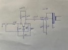
EL84 SEP amplifier

Well, @atmasphere : for my curiosity, would you draw a sketch about the solution you are thinking about ? To be honest, I'm not sure to have much more room than in your little box... :confused: In my schematic, the upper triode of the ECC83 already acts - in theory - as a plate load, current regulator and low output impedance. ;)

T
SEPBalanced.jpg
The idea is just to run a balanced input; if the amp is a monoblock the advantage is it can sit right by (or on) the speaker so the speaker cable can be kept short. Instead you run a long interconnect since you can do that with balanced lines.

The CCS just dispenses with the need to run different value plate loads to compensate for the mu of the tube. Instead you match them.
I may also experiment with a cathode load for the EL84 in triode connection, instead of the UL connection. If the DCR of the output transformer is of the suitable value to offer the expected cathode bias, it could be fun :

View attachment 3636657

T
If you do that, the primary winding will be about 1/4th the normal plate load.

All the gain will occur in the Voltage amplifier, so you might reconsider that circuit and run a cascode instead. You can do this since the input capacitance of the EL84 is quite low in CF mode (so its input impedance is very high). I think you'll find that triode or pentode, when in CF mode the distortion won't change much. If you set up the cascode correctly, you might have enough gain that you can run it in ultra linear mode, biasing the top grid using a divider network as I did in the EF86 circuit of the amp that started this thread.
 
@atmasphere I'd like to understand clearly about injecting the GNFB into the first stage grid. Are you connecting the 27k feedback resistor directly to the grid or on the input side of the 4.7k stopper? If you will eventually publish some screen captures of your square waves and distortion spectra that would be really nice.
Thanks,
John
The feedback resistor ties directly to the grid so the input signal is coming through the stopping resistor before it encounters the feedback.

This requires the output be inverted but that's no problem with the OPT.

I like to do it this way to avoid the feedback signal being distorted by the tube as the mixing is occurring.

Once I've got the amp properly neutralized (I've been pretty busy lately) I'll put it on the bench and put it thru its paces.
 
You could also tie EF86's plate load to the OPT screen tap. I have not tried applying any FB to the input pentode g2 yet...those I leave as pentodes( even if it is a 'built' pentode; aka cascode ).

Douglas
 
If the DCR of the output transformer is of the suitable value to offer the expected cathode bias, it could be fun :
I always wanted to try that on something. Probably why I think Circlotron amps are interesting, those are sort-kinda this but in a push-pull version. Or awful similar to a totem pole solid state amp, however you prefer to look at it. I just never wanted to fool with the power supply those amps require.
 
You could also tie EF86's plate load to the OPT screen tap. I have not tried applying any FB to the input pentode g2 yet...those I leave as pentodes( even if it is a 'built' pentode; aka cascode ).

Douglas
I've been considering that. Now that I'm done with my RCA RS193 project I'll be look into this.
I may also experiment with a cathode load for the EL84 in triode connection, instead of the UL connection. If the DCR of the output transformer is of the suitable value to offer the expected cathode bias, it could be fun
One thing I forgot to mention about this is that most of the distortion is likely to occur in the Voltage amplifier rather than the output section. Our OTLs are essentially a cathode follower output (Circlotron) and it really only makes about 5% of the distortion of the amp.

The remaining 95% comes from the Voltage amplfier, since it has to make a pretty large Voltage swing to drive the amp to full output. This is because there is Voltage lost driving the power tube, and in the case of an SEP there's also a Voltage loss due to the OPT. So that Voltage swing is a pretty big ask.

That is why I recommended a cascode, so you could get the most Voltage swing possible. But the cascode is higher distortion than the SEPP you proposed. Alternatively if the SEPP is optimized for Voltage swing you might be able to pull it off. But since the EL84 is a CF, it will be very easy to drive with negligible input capacitance so the cascode seems to me the better option.

You can set a fairly high plate load, 221K or higher to get the swing you need. The gain variables will be the bias in the top grid and the cathode resistor. All the work I've done suggests the top grid (which is in effect the plate Voltage of the bottom tube) not be very high since most of the swing has to be done by the top tube.

FWIW, if you load the output transformer with a lower impedance the primary side will express a lower impedance too. This might be one way of finding an OPT that has a gapped core that would be the right impedance, if it has a 16 Ohm tap you could load it at 4 Ohms and hit the target.
 
Cascode is not the way to get the most voltage output from a given B+. The lower element needs some un-recoverable voltage in which to operate. You can remove the need to double that amount by running a MOSFET on top. That works quite well IME... :)

There are some entertaining ways to run plate-to-grid FB to reduce distortion without wrecking the high input Z of the stage. Contemplating that for the HY51A amplifier...but it will likely just get a triode and a slight step-up input TX.

Douglas
 
Cascode is not the way to get the most voltage output from a given B+. The lower element needs some un-recoverable voltage in which to operate. You can remove the need to double that amount by running a MOSFET on top. That works quite well IME... :)
What is meant by 'the need to double that amount'?
 
What is meant by 'the need to double that amount'?
The plate voltage of the lower element, set by the grid voltage of the upper allows a certain amount of current at its zero bias point. In order to actually flow that much current, the upper needs an equal amount of voltage. This is shown in the roughly horizontal plate curves of the cascode( where that condition is met). I will see if I can find the graphic I cooked up while looking at 'what the heck is going on with a cascode' that shows this pretty easily.

The usual solution is to substitute a MOSFET for the upper element; then you can swing the 'plate' of the upper element very close to where its 'grid' is referenced. Or a lower plate resistance triode, but that *GENERALLY leaves enough signal at the upper cathode that Miller comes back into play( at least part way; the low input capacitance of the composite is lost ).

Take a 6BQ7 data sheet that shows the cascode plate curves. Cut out and re-size the standard triode curves up to the reference voltage of the cascode. Lay this plate curve over the cascode, origins aligned. Take a second copy and lay its origin on the reference voltage. Observe where the horizontal plate curves begin with respect tot eh second set of triode curves...what do you see?

Douglas
 
Last edited:
The plate voltage of the lower element, set by the grid voltage of the upper allows a certain amount of current at its zero bias point. In order to actually flow that much current, the upper needs an equal amount of voltage. This is shown in the roughly horizontal plate curves of the cascode( where that condition is met). I will see if I can find the graphic I cooked up while looking at 'what the heck is going on with a cascode' that shows this pretty easily.

The usual solution is to substitute a MOSFET for the upper element; then you can swing the 'plate' of the upper element very close to where its 'grid' is referenced. Or a lower plate resistance triode, but that *GENERALLY leaves enough signal at the upper cathode that Miller comes back into play( at least part way; the low input capacitance of the composite is lost ).

Take a 6BQ7 data sheet that shows the cascode plate curves. Cut out and re-size the standard triode curves up to the reference voltage of the cascode. Lay this plate curve over the cascode, origins aligned. Take a second copy and lay its origin on the reference voltage. Observe where the horizontal plate curves begin with respect tot eh second set of triode curves...what do you see?

Douglas
I found that Valley and Wallman's (who literally 'wrote the book on it') assessment was correct. In practice, we found that keeping the bottom tube at a fairly low plate Voltage while also having a relatively high plate load resistance for the top tube was the most effective for producing a large Voltage swing from the top tube.

I am open to the idea of a MOSFET for the top location. By all accounts it does seem to be a good way to deal with the circuit.

I didn't find a data sheet on the 6BQ7 that showed cascode curves. Do you have a link?
 
Back
Top Bottom