• The move to the new server is done. There are some software and database maintenance updates in process. This has us passing the hat around to help out. We appreciate any donations. Seriously, even a dollar helps. The payment page may be found here - https://www.audiokarma.org/support.html

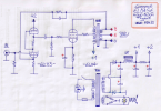
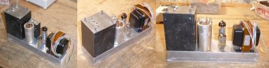
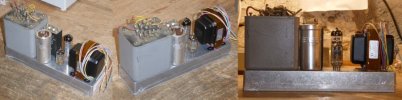
EL84 SEP amplifier

There's a bit of ringing

Oh, I suggest you to also place a 1K5 to 4K7 resistor in serie with the grid of the EL84 or EL86 - just to test if the oscillations stops. An old, common solution... ;)

The EL86 is an interesting alternative here : it needs less voltage than the EL84, and its 9W plate dissipation is convenient with your circuit parameters... :cool:

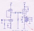
I see that your EF86 is connected in some kind of pseudo-triode by the 2x150K screen divider tied to the plate. I order to reduce the overal gain, why not connect the EF86 preamp directly in triode connection finally ? You would then have less feedback, so more stability, if the only purpose is to tame the excess of gain...

Looking at you schematic, I see that you did not referenced to GND the heater winding (maybe a simple drawing omission ?) : a pair of 100R/1W resistors placed across the EL86 socket may improve the hum ratio of you amp. Below, with an ECC83, in one of my DIY guitar amps :
1762897105156.png1762897143925.jpeg

But these are my suggestions, OK ? It's your amp, and you decide accordingly ! ;)

T
 
Oh, I suggest you to also place a 1K5 to 4K7 resistor in serie with the grid of the EL84 or EL86 - just to test if the oscillations stops. An old, common solution... ;)

The EL86 is an interesting alternative here : it needs less voltage than the EL84, and its 9W plate dissipation is convenient with your circuit parameters... :cool:

I see that your EF86 is connected in some kind of pseudo-triode by the 2x150K screen divider tied to the plate. I order to reduce the overal gain, why not connect the EF86 preamp directly in triode connection finally ? You would then have less feedback, so more stability, if the only purpose is to tame the excess of gain...

Looking at you schematic, I see that you did not referenced to GND the heater winding (maybe a simple drawing omission ?) : a pair of 100R/1W resistors placed across the EL86 socket may improve the hum ratio of you amp. Below, with an ECC83, in one of my DIY guitar amps :
There is already a 4.75K stopping resistor at the grid of the EF86 as seen in the schematic. Its been there since the inception of this project. Now its doing double duty similar to the series input resistor in an opamp circuit. You need the stopper resistor for the feedback scheme to work.

I wanted the extra loop gain which is why I went with the EF86. In triode mode I might as well run a 12AX7 or the like. As it sits the EF86 has a bit more gain.

Its pretty clear the feedback has reduced the distortion substantially as I can see the increased sine symmetry on the 'scope. Tomorrow if I have time I'll see what the analyzer thinks of it. In the meantime the amps have been playing in the shop system and seem to work rather well.
 
I wonder if maybe you could bring the feedback in to the screen instead of the grid. Maybe put together a voltage divider off the UL or plate feeds from the output tube. If the AC voltage ends up too high you could make the resistor from EF86 screen to ground two resistors in series with one bypassed with a cap. Adjust the ratio of bypassed vs un-bypassed to get the right AC signal without changing the DC operating point.
 
The feedback has to be out of phase with the signal on the control grid. The power tube inverts the phase, so feedback from it to the screen would be positive feedback.
 
Inspired by your compact units, @atmasphere, my next compact EL84 Mono-Block amps will look like this - with a more conventional design, though ;) :

1763060570438.png

Chassis should be Hammond 1590BX2...

1763060776503.png

... Unless I could find the same boxes as yours ? Would you remind me the Hammond references you used ? :)

T
 
... Unless I could find the same boxes as yours ? Would you remind me the Hammond references you used ? :)

T
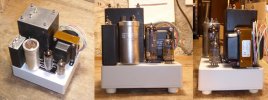
They are Hammond boxes; PN 1444-542 5" x 4" x 2. I had to special order them (thru CE Distribution). https://www.hammfg.com/electronics/small-case/chassis/1444

I then sorted out the layout, punched and drilled the chassis. Then I took the power transformer and output transformer end shells off and had them all powdercoated in a black wrinkletex finish.

I forgot to send the bottom covers along. I need to drill a hole pattern in them just to let a bit of air in. But I have all the parts rated well so there's not much in the way of heat generation inside the chassis.

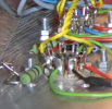
I had to wire a good deal of the EF86 socket prior to installing it. I used the center pin (which not all 9-pin sockets have) as ground for the grids and cathode, so any hum or noise on the wire going to audio ground would be common mode and so not amplified (as much). To save room some of the terminal strips share mounting hardware with the tube sockets. I also used some of the transformer mounting hardware to also hold terminals in place.

The audio ground is floating via a 100 Ohm resistor at chassis ground potential. This required that there were no chassis ground connections used anywhere except that 100 Ohm resistor.

I mounted the Hammond 155 5H choke to one side of the chassis. There really wasn't enough room in the whole thing :)

I found a nice compact toggle switch for the AC power. It sits just below the power supply filter cap so had to be wired almost last. I wired the choke last, since it blocks so much access.
 
I see - Thanks @atmasphere !

This :

1763073449260.png

I could be able to find them via Mouser Electronics France :

1763073564179.png

I did not remember if you posted an inside view of your little amps : I'll have to scroll the thread to see.
EDIT : no, there's none - would you mind posting one, then ?

Then I took the power transformer and output transformer end shells off and had them all powdercoated in a black wrinkletex finish.

This finish is fine looking, and certainly abuse-resistant moreover. I'm not sure if I could do the same here in France...

T
 
would you mind posting one, then ?
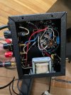
SEPInside.jpg
I screwed up on this one although its a bit neater as its the second channel. I meant to have the RCA connector where the fuse and power cord are so I had to run shielded wire to the input of the EF86, which I did not do in the other channel which simply uses a twisted pair.
The resistor connected to the red speaker connection is the feedback resistor. It still needs a compensation capacitor.
 
I see - thanks @atmasphere :cool: !

I just wanted to see where you placed the Hammond 155 choke, and how you organized the wiring all around. I understand why your box had to be thicker, in order to house the non-visible choke.

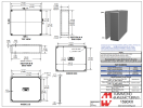
An alternative for me could be that die-cast box :

1763146824146.png

A bit larger with 145x121mm instead of your 127x101mm folded chassis, but 35mm thick instead of 52mm, assuming I could place the choke outside... I'll have to trace it with my parts to check...

T
 
I see - thanks @atmasphere :cool: !

I just wanted to see where you placed the Hammond 155 choke, and how you organized the wiring all around. I understand why your box had to be thicker, in order to house the non-visible choke.

An alternative for me could be that die-cast box :


A bit larger with 145x121mm instead of your 127x101mm folded chassis, but 35mm thick instead of 52mm, assuming I could place the choke outside... I'll have to trace it with my parts to check...

T
If I had it to do over I'd do the same thing (although I'd still get it painted. The lip around the edge of that box made it difficult to work inside. I don't like doing messy work.
 
If I had it to do over I'd do the same thing (although I'd still get it painted. The lip around the edge of that box made it difficult to work inside. I don't like doing messy work.

That's true : the surround lips of the folded box are absent on the die-cast one, and yes it allows a better access to the inside for installing and wiring, as these chassis are very compact - notably your folded one !

I must say that your structured "swirling" black paint is mighty cool, making me think about military equipements... :cool:

Let me trace with the elements I have on hand and be back - just for the curiosity ! :) ;)

T
 
Not to hijack @atmasphere 's thread, OK ? - But here are three possible layouts simulations - with the parts I have on hands - for a similar pair of compact EL84 SE mono-blocks...

1 - With Hammond 1590XX box and 160V/100mA Xfo : The closest approach to atmasphere's models...

1763330585708.jpeg

2 - With Hammond 1590BX2 box and 160V/100mA Xfo : a slender version, narrower and longer...

1763330605801.jpeg

3 - With Hammond 1590BX2 box and 500VCT/60mA Xfo : a slender version too, with another PT...

1763330625321.jpeg

What do you think ? :biggrin:;)

T
 
Last edited:
Not to hijack @atmasphere 's thread, OK ? - But here are three possible layouts simulations - with the parts I have on hands - for a similar pair of compact EL84 SE mono-blocks...

1 - With Hammond 1590XX box and 160V/100mA Xfo : The closest approach to atmasphere's models...


2 - With Hammond 1590BX2 box and 160V/100mA Xfo : a slender version, narrower and longer...


3 - With Hammond 1590BX2 box and 500VCT/60mA Xfo : a slender version too, with another PT...


What do you think ? :biggrin:;)

T
Fabulous! Please proceed.

Here's a thing to think about, something for which I didn't have the room. If the input circuit was a 12AX7 or 12AT7, it could be set up as a differential amplifier, allowing a balanced input. This would allow for a longer cable run so the amp could have the shortest speaker cable possible, which is important for tube amps with a high output impedance. To do that would require some sort of negative supply, such as a 6V supply which might also be the filament supply. That would be enough that you could run a very competent Constant Current Source (CCS) in the cathode circuit of the 12A_7 circuit.
 
Well, @atmasphere : for my curiosity, would you draw a sketch about the solution you are thinking about ? To be honest, I'm not sure to have much more room than in your little box... :confused: In my schematic, the upper triode of the ECC83 already acts - in theory - as a plate load, current regulator and low output impedance. ;)

T
 
@atmasphere I'd like to understand clearly about injecting the GNFB into the first stage grid. Are you connecting the 27k feedback resistor directly to the grid or on the input side of the 4.7k stopper? If you will eventually publish some screen captures of your square waves and distortion spectra that would be really nice.
Thanks,
John
 
I may also experiment with a cathode load for the EL84 in triode connection, instead of the UL connection. If the DCR of the output transformer is of the suitable value to offer the expected cathode bias, it could be fun :

1763490023590.png

T
 
Back
Top Bottom