• The move to the new server is done. There are some software and database maintenance updates in process. This has us passing the hat around to help out. We appreciate any donations. Seriously, even a dollar helps. The payment page may be found here - https://www.audiokarma.org/support.html

First Power-up in 55 Years - Need Advice

Post the schematic of the original build if you have it or at least pics of the units for comment. Some of the early OTLs derived their B+ straight off the AC mains and did not use an isolation transformer. Depending on how they were built they could be hazardous if you aren't aware of that.
I have posted a few photos. I'll get more up soon. These units do have an isolation transformer - one of the biggest I've ever seen.
 
Great score! And judging by the size of those transformers,if you don't like them as amps you could always convert them to welding machines.Bet the car rode real smooth with those in the trunk:)
All four chassis (2 power supplies and 2 power amps) came mounted on a board with wheels on the bottom. When I went to pick it up, I was a bit surprised to say the least. I would guess 120 lbs. I'll have to throw them on a scale.

Thanks,
 
Quite simple really. Just measure across the output terminals to determine if,and how much,DC voltage is appearing. The best is obviously 0 volts,but is not always achievable,even with solid state gear. Not knowing these units,I really couldn't give you an exact value,or if they even have adjustments for this.

I'm guessing you live somewhere with a cool climate and very reasonable electric rates?:rolleyes:
I did measure the DC voltage on the outputs. On the right channel, I read .01 VDC. This is about half way between 0 and "pinned" on the built-in offset meter. On the left side, the meter is pinned and I read about 3.4 VDC. I have the bias dialed in at -20V. There is a balance pot for adjusting the offset, but turning the dial seem to do little to nothing on either side.
I'm guessing the right channel is usable at .01V, but i'll keep working on both of them.

Thanks,
Joe Y
 
Are the tubes laid out in logical way that you can move tubes from the "positive" to "negative" side to balance the offset?
On Carver's 200 watt amp there are 8 6550's in each channel,there is a procedure in the manual
for the balancing procedure,mixing and matching tubes for balance
 
Are the tubes laid out in logical way that you can move tubes from the "positive" to "negative" side to balance the offset?
I assumed they would be, but it is easy enough to verify by looking at the underside wiring.
I could take a low-tech approach and just swap 1/2 of the negative tubes with half of the positive tubes and then test the offest
I was also thinking about building a small tube tester and get a reading on each tube. Something like this: Simple-Valve-Tube-Tester/
I could then group them according to their test values and make up balanced sets.
 
I know a little about tube testers but I'm not sure exactly what test you would be performing here. Is this something that could be tested by at least some tube testers? If there is a tester out there with that function, you could always ship all the tubes to someone and have them tested. I'm thinking one of the higher end ones like the 539c.
 
Good grief,60 12B4's to test?! Two thoughts occur: Disable the B+ and use the amp as a preheating rack,otherwise this is going to take a whole lot of time,and install a socket-saver on your tube tester.

Keep in mind that many tubes will not show leakage or gas until they are thoroughly heated,meaning very close to their actual operating temperature,a point that is missed by many people.A ten second toasting in the old checker is just not enough.
 
I did measure the DC voltage on the outputs. On the right channel, I read .01 VDC. This is about half way between 0 and "pinned" on the built-in offset meter. On the left side, the meter is pinned and I read about 3.4 VDC. I have the bias dialed in at -20V. There is a balance pot for adjusting the offset, but turning the dial seem to do little to nothing on either side.
I'm guessing the right channel is usable at .01V, but i'll keep working on both of them.

Thanks,
Joe Y

The 0.01 VDC reading is pretty darned good,even by solid state standards. The 3.40 VDC is going to require some investigation. If something were seriously amiss,you'd likely be seeing a lot more.My guess,as the balance control has no effect,would be a leaky coupling cap or bad output tube.I'd really like to see a schematic:)
 
My guess,as the balance control has no effect,would be a leaky coupling cap or bad output tube.I'd really like to see a schematic:)
I have not touched any of caps yet so I could very well have a leaker.
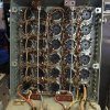
I'll take a closer look at the tubes and see if there is anything obviously weird with any of them. I also want to clean all the tube sockets (all 630 of them).
 
It could even be off-balance tubes. The mention of shuffling tubes around may be your answer, but of course being old gear it could be a lot of other things as well.
 
Whoa, just caught this thread for the first time...

Those amps are simply Fanfriggintastic! Super cool.
 
I just discovered this super cool feature: the tube array is built on a hinged platform. What a great idea! Just remove 2 screws and the top flips over exposing the underside of the socket cluster.
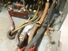
I also discovered some badly damaged insulation on the filament wires. I'll have to replace those before I power up again.
 

Attachments

  • 2016-06-02 18.49.14.jpg
    2016-06-02 18.49.14.jpg
    93.2 KB · Views: 77
  • 2016-06-02 18.49.22-2.jpg
    2016-06-02 18.49.22-2.jpg
    89.7 KB · Views: 75
  • 2016-06-02 18.49.30.jpg
    2016-06-02 18.49.30.jpg
    95.5 KB · Views: 77
  • 2016-06-02 18.49.36.jpg
    2016-06-02 18.49.36.jpg
    82.7 KB · Views: 74
  • 2016-06-02 18.49.55.jpg
    2016-06-02 18.49.55.jpg
    91.1 KB · Views: 76
  • 2016-06-02 18.50.47.jpg
    2016-06-02 18.50.47.jpg
    107.2 KB · Views: 78
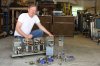
Here are a few more photos.
You can see in a couple of the photos the matching preamps and their power supplies.
I purchased these, along with the custom made Bozak speakers about 8 months ago in a totally unrelated deal.
You can also see a constant voltage power supply that is also sporting the MP Engineering logo - it came with the amps.
And oh yeah - there is also a 3rd OTL amp and power supply. This one was thrown in the deal - no charge!
Sometimes things just work out. I think this is one of those times.
My head is spinning as I try to absorb all of this awesomeness!
 

Attachments

  • IMG_7399.JPG
    IMG_7399.JPG
    88.8 KB · Views: 76
  • IMG_7405.JPG
    IMG_7405.JPG
    69.7 KB · Views: 73
  • IMG_7406.JPG
    IMG_7406.JPG
    79.8 KB · Views: 76
Last edited:
While replacing all the frayed wire inside, I would replace all the lytics in there at the same time. You just can't deal with the unknown X,Y,Z all together so eliminate all the 50 years old problem caps out of the equation first.

On the upside, the 12B4 tubes are reasonably cheap on the big auction site. Not sure how long it's gonna stay cheap, I would just get a couple hundreds NIB 12B4 for the future sake.
 
Back
Top Bottom