


I'm on my 2nd rebuild of a Fisher 400 ser. 57308, and have some concerns on startup after completing the replacement of all the can sections on the receiver. I purchased a kit from Hayseed Hamfest as I had on my first 400 rebuild. I've never started up this 400 prior to replacing the can section caps and bias supply. I cleaned all switches, controls, pots, sockets, and tested tubes prior to startup after cans were replaced.
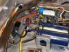
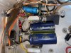
I've replaced the large yellow bias supply can with a pair of 1000uf 63V caps and wired them up to the silicon rectifier and ground with the help of another AKr diagram. I tied both neg ground leads together and connected them to the -side of bridge, heaters (yellow wire) and Bias B- (to resistor that connects to the terminal nearby with gray wire that connects to 330K grid resistors terminal). One positive lead I tied to ground, the other to the + side of bridge rectifier. I think I've done this correctly but would appreciate feedback.
I started up the receiver on a DBT connected to my variac and watched for excessive current draw on the bulb and didn't see any so I went to the variac alone, starting at 30VAC and moving up to about 50VAC. I noticed the plate voltage at pin 9 rising steadily to about 200 VDC as I increased the variac to about 50 VAC, but the screen voltage at pin 1 staying low at around 15 VDC when the variac was moved up to 50 VAC.
I'm concerned somethings not right, the large 1.2K 7W resistor coming from the output trannies to pin 1 on V15 is getting hot and smelling smokey when its around 15 VDC. I didn't replace the selenium bridge rectifier at this point because I read these silicon bridge rectifiers don't have a tendency to fail. I'm connecting 4 ohm test speakers to the receiver while testing Using 7868 tubes while testing, tubes tested good, but not matched.
I've replaced the large yellow bias supply can with a pair of 1000uf 63V caps and wired them up to the silicon rectifier and ground with the help of another AKr diagram. I tied both neg ground leads together and connected them to the -side of bridge, heaters (yellow wire) and Bias B- (to resistor that connects to the terminal nearby with gray wire that connects to 330K grid resistors terminal). One positive lead I tied to ground, the other to the + side of bridge rectifier. I think I've done this correctly but would appreciate feedback.
I started up the receiver on a DBT connected to my variac and watched for excessive current draw on the bulb and didn't see any so I went to the variac alone, starting at 30VAC and moving up to about 50VAC. I noticed the plate voltage at pin 9 rising steadily to about 200 VDC as I increased the variac to about 50 VAC, but the screen voltage at pin 1 staying low at around 15 VDC when the variac was moved up to 50 VAC.
I'm concerned somethings not right, the large 1.2K 7W resistor coming from the output trannies to pin 1 on V15 is getting hot and smelling smokey when its around 15 VDC. I didn't replace the selenium bridge rectifier at this point because I read these silicon bridge rectifiers don't have a tendency to fail. I'm connecting 4 ohm test speakers to the receiver while testing Using 7868 tubes while testing, tubes tested good, but not matched.
Attachments


Last edited:
