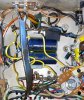
Resistors tested in circuit will usually show low due to the rest of the circuit. Best to lift one leg out of the circuit and test. I seriously doubt they are the problem with bias. If you left in C42, R34, & R35 There's your problem with the bias voltage being a bit low 1st off let me know what the voltage actually is at the NEGATIVE Terminals on the BIAS CAP(s). Take all 3(C42,R34,R35) out and put a 10K pot in place of R35. Tie legs 1 and 2 together on the pot and solder to the bias cap side, with pin 3 on the pot going to the tube side. Tying legs 1 & 2 together now make the pot a variable resistor. Now you have a global voltage adjustability. Power it up without the power tubes and check the voltage at pin 2. Adjust the pot so pin 2 reads -17.V. This will be your base line. Turn it off, insert the tubes, and power up. readjust pin 2 voltage to -17V. Take bias reading @ 2-3 minutes, Adjust highest tube to 400mv. The rest will all be lower. Now you have some control of Bias voltage. Now to get better matching tubes in there. Leave the voltage @ -17v. Change tubes, power up and take measurements. Number the tubes, and note readings at -17V. If we can get 4 1/2way tight measuring tubes in there, you should be ok until you build an IBAM and install it. Then you can match the tubes for load, vs. voltage.
With a late model 400 the power transformer voltages will be a little lower than schematic. Your's are in the ballpark of expectations. Heater voltages good. Bias voltage a little low.
At this point Swap V14 and V16. This will even them up a little. V17 at the voltages you're showing me is running a bit over max dissipation @ 19.25W plate dissipation. With 3ma subtracted for screen it's down to 18.12W (about 93% total dissipation). NOT GOOD!
Overall dissipation per tube
V14 = 14.62W
V15 = 14.43W
V16 = 12.37W
V17 = 18.08W
Definately need's an IBAM installed. A 10K resistor inline on the bias power lead isn't going to cut it. The disparity between the high and the low tubes is too much. V16 with a bias voltage of -16 is a Red Hair shy of 65%.
Mark the high and low tubes. If you have 2 other decent tubes, put them in and fire it up. Check bias after 10 minutes. All 4 tubes and let me see what you get. Save the tube marked V17 at all costs, it's REALLY GOOD if it's an old stock tube. Swap the tubes around pair to pair until you get 2 closely matched pairs (you don't have a way of adjusting YET, so this is best way).
With a late model 400 the power transformer voltages will be a little lower than schematic. Your's are in the ballpark of expectations. Heater voltages good. Bias voltage a little low.
At this point Swap V14 and V16. This will even them up a little. V17 at the voltages you're showing me is running a bit over max dissipation @ 19.25W plate dissipation. With 3ma subtracted for screen it's down to 18.12W (about 93% total dissipation). NOT GOOD!
Overall dissipation per tube
V14 = 14.62W
V15 = 14.43W
V16 = 12.37W
V17 = 18.08W
Definately need's an IBAM installed. A 10K resistor inline on the bias power lead isn't going to cut it. The disparity between the high and the low tubes is too much. V16 with a bias voltage of -16 is a Red Hair shy of 65%.
Mark the high and low tubes. If you have 2 other decent tubes, put them in and fire it up. Check bias after 10 minutes. All 4 tubes and let me see what you get. Save the tube marked V17 at all costs, it's REALLY GOOD if it's an old stock tube. Swap the tubes around pair to pair until you get 2 closely matched pairs (you don't have a way of adjusting YET, so this is best way).
Last edited: