• The move to the new server is done. There are some software and database maintenance updates in process. This has us passing the hat around to help out. We appreciate any donations. Seriously, even a dollar helps. The payment page may be found here - https://www.audiokarma.org/support.html

Fisher 400 startup issues after rebuild

Yes the Negatives tied together on the dual 1000uf caps is your bias voltage going to the tubes at the beginning. Follow that lead to the 300K grid return resistors and measure voltage there on all 4 resistors, and again at pins 2/6 on the output tube sockets. I want to make sure you have bias voltage at the tubes that is commensurate with what is output at the bias caps.

Pins 4 & 5 on the output tubes are the heater pins. They should be 6vAC or so across the pins. One probe on 4 one probe on 5. They will be slightly higher with out the tubes in.
 
Last edited:
Yes the Negatives tied together on the dual 1000uf caps is your bias voltage going to the tubes at the beginning. Follow that lead to the 300K grid return resistors and measure voltage there on all 4 resistors, and again at pins 2/6 on the output tube sockets. I want to make sure you have bias voltage at the tubes that is commensurate with what is output at the bias caps.

Pins 4 & 5 on the output tubes are the heater tubes. They should be 6vAC or so across the pins. One probe on 4 one probe on 5. They will be slightly higher with out the tubes in.
Got it. Will power up without the output tubes and variac at 117VAC for reading these values.
 
If voltages check out on this testing, chances are very good you have a tube that's shorted and drawing an inordinate amount of amps. Have them checked for shorts period. Also tighten up all of the socket leaves, there may be a loose one and not making contact. What tubes are you using? Old Stock 7868 or Newer Russian EH7868's?

Do you have another quad of 7868's handy?
When I first tested this with tubes I probably had a bad 7868 in the mix. I've retested them and replaced with what I think are good. I'm using a B&K 747 tester. I have a quad of reasonably good 7868 old stock. I'm avoiding EH to keep my sockets stock. Been there done that.
My voltages are:
Neg junction of bias caps = -26.3 VDC
330K resistors all read -17.8 VDC
All 4 output sockets read close
Pin 1 = 400 VDC
Pin 2 = -17.3 VDC
Pin 9 = 428 VDC

EDIT: Tested at 117 VAC
 
Voltages are good. They'll come down a little when you put tubes in it.

I don't see from pics in post 1, a.) Cathode resistors from pin 3 to ground, 10Ω 1/4w. b.) Screen stability resistors, 100Ω 1/4W between buss line and pin 7 or 1. These I would strongly recommend (as bare minimum protection against arcing in the tubes) BEFORE powering it up any further. See post #39 and 40 in the thread "Common parts for FISHERs" in the Stickies.
I am planning to install the cathode sensing 10 ohm and the 100 ohm grid stopper resistors.

Would it be safe to startup with tubes after doing that?

my plan moving forward is toI replace the screen 330k with 200k 1/2W resistors at the same time, as installing .1uf 600V coupling caps.

Should the 330K grid resistors be changed to 200K 1/2W at the same time as the 10Ω and 100Ω or wait until the IBAM is installed?
 
Last edited:
I am planning to install the cathode sensing 10 ohm and the 100 ohm grid stopper resistors.

Would it be safe to startup with tubes after doing that?

my plan moving forward is toI replace the screen 330k with 200k 1/2W resistors at the same time, as installing .1uf 600V coupling caps.

Should the 330K grid resistors be changed to 200K 1/2W at the same time as the 10Ω and 100Ω or wait until the IBAM is installed?
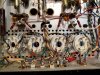
Question on installing the cathode sensing resistors; First, I remove daisy chain jumper wires from pins 1 and move them to pin 8. Next, I move R41 lead from pin 1 to pin 8. There are 2 resistors I've pointed out in red on sockets V14 and V16. Last time I did this I ran into trouble. Should I leave the resistor on the left side (V16 pin 4 to ground) and replace the jumper at pin 3 with the 10Ω resistor, correct? On the resistor at the right side of photo that is tied between pin 5 and pin 3 V14, I will remove one leg from pin 3 and tie it to ground, then install the 10Ω to ground from pin 3. I'll end up with 4 10Ω resistors between pin 3 and ground. This is how I did my previous early version ser. 28xxx 400.
 

Attachments

  • IMG_2748.JPG
    IMG_2748.JPG
    187.4 KB · Views: 10
Here's how I did one of my 400's. This one had new sockets so I was starting from scratch but, you get the gist. The 10 watt resistor is tied in at the far left socket since it had long leads.


20220430_174250.jpg
 
Question on installing the cathode sensing resistors; First, I remove daisy chain jumper wires from pins 1 and move them to pin 8. Next, I move R41 lead from pin 1 to pin 8. There are 2 resistors I've pointed out in red on sockets V14 and V16. Last time I did this I ran into trouble. Should I leave the resistor on the left side (V16 pin 4 to ground) and replace the jumper at pin 3 with the 10Ω resistor, correct? On the resistor at the right side of photo that is tied between pin 5 and pin 3 V14, I will remove one leg from pin 3 and tie it to ground, then install the 10Ω to ground from pin 3. I'll end up with 4 10Ω resistors between pin 3 and ground. This is how I did my previous early version ser. 28xxx 400.
Which terminal wires should the CL-80 be connected to? I'm not sure I'm clear on how it connects. Could you point out where it connects and which if any wires get removed from the terminal? Thanks
 

Attachments

  • IMG_2749.jpg
    IMG_2749.jpg
    127.4 KB · Views: 15
Lift the (left) tan A.C. cord from the terminal strip. Solder one leg of the cl80 to that terminal where the existing brown cloth covered wire is. Re-connect (solder) the A.C. line to the other cl80 leg. Done!

The end result - The cl80 is now in series with the AC line and the On/Off switch.

The cl80 has no polarity. It gets hot so lean it away from other wires.
 
Last edited:
Lift the (left) tan A.C. cord from the terminal strip. Solder one leg of the cl80 to that terminal where the existing brown cloth covered wire is. Re-connect (solder) the A.C. line to the other cl80 leg. Done!

The end result - The cl80 is now in series with the AC line and the On/Off switch.

The cl80 has no polarity. It gets hot so lean it away from other wires.
Got it. Thanks
 
Got it. Thanks
Here's what I have so far, after installing the 10Ω cathode sensing resistors and moving the daisy chain from pins 1 up to pins 8. Installed the CL-80 and tested with no output tubes, DBT at 117 VAC first then with it plugged into the wall, read 403 VDC at pin 1, 430 VDC at pin 9.
 

Attachments

  • IMG_2750.jpg
    IMG_2750.jpg
    147.5 KB · Views: 23
Last edited:
Voltages are good. They'll come down a little when you put tubes in it.

I don't see from pics in post 1, a.) Cathode resistors from pin 3 to ground, 10Ω 1/4w. b.) Screen stability resistors, 100Ω 1/4W between buss line and pin 7 or 1. These I would strongly recommend (as bare minimum protection against arcing in the tubes) BEFORE powering it up any further. See post #39 and 40 in the thread "Common parts for FISHERs" in the Stickies.
Larry, I'm not seeing any AC voltages across Output Tube heater pins 4 and 5. No tubes installed at this point, all cathode resistors installed along with screen stability resistors, daisy chain moved from pins 1 to pins 8.
Looks good!

I found a photo of that cl80 install.

View attachment 2799635
Am I correct to assume I can read bias current across the 10Ω cathode sensing resistors?
 
HEATERS for OUTPUT TUBES
Did you move the 2 - 220Ω (R36 & R37) resistors from the output tubes pin 3 (one on each pair) and run them to a separate ground when the 10Ω cathode resistors were installed?????? If not you need to do both

Even if you don't have the tubes in you should get a reading on the sockets. one of two things is wrong. A bad solder joint back further, a broken wire somewhere in the chain, or a bad winding in the transformer.(pray it ain't that!).

Pull the schematic, and do continuity tests on each side of the circuit, (the furthest connection, to the 1st connection on the transformer). Test each succesive closer in connection until you get a good reading/beep. Then troubleshoot the problem area. Also check continuity on the transformer windings.

Reading off the 10Ω resistors
You read millivolts(mv) across the 10Ω cathode resistor, and convert it to milliamps(ma) by dividing the mv by the value of the cathode resistor. for example..... .300v or 300mv / 10Ω = 30ma
 
Last edited:
Get hold of your 4 best testing tubes (they CAN be mixed brands) and put them in. Bring it up on DBT (start variac at 60V), ramp up to 120V on the variac. If the lamp brightens slightly in concert with voltage increase (controls centered, Volume to ZERO, speakers connected) and does not go bright, check plate and screen voltages, heater voltages on the DC voltage heaters (the 4 off the bias circuit) which should be between 5.5 and 6.0 on DBT. If all checks out, shut it down for 10 minutes and remove DBT. Power back up to 117v and recheck above voltages. If ok and heaters are 6.3 or 12.6 + or - 5%, button it up and run it for a few hours and check the bias @ 15 minutes, and after an hour.
 
`

My bad. My meter probes were screwed up, I was able to read 6.3 VAC across pins 4 and 5 just fine, didn't realize the post on this went through till now.
With the old stock 7868s the plate is reading 389 VDC screen reads 349 VDC, checked it again at wall (123VAC) plate was 408VDC screen 365VDC Checked bias and it seemed high on some tubes 290 mv-400 mv. Sounds great, no hum. Going to read the bias on each tube again and post back. I'll be installing the 200k grid screen resistors, .1uf 600V russian PIO, and IBAM at the end of this week. I checked V10 voltage, and it was -24.8 VDC pin 5 I think.
 
With the old stock 7868s the plate is reading 389 VDC screen reads 349 VDC, checked it again at wall (123VAC) plate was 408VDC screen 365VDC Checked bias and it seemed high on some tubes 290 mv-400 mv. Sounds great, no hum. Going to read the bias on each tube again and post back. I'll be installing the 200k grid screen resistors, .1uf 600V russian PIO, and IBAM at the end of this week. I checked V10 voltage, and it was -24.8 VDC pin 5 I think.
I read bias after playing for a half hr or so. V14 = 406mv, V15 = 401mv, V16 = 348mv, V17 = 495mv. Seems pretty high overall.
EDIT: Powered off variac at 117 VAC, pin 2 reading on all 4 original 7868 read -16.1 VDC. Plate is 389 VDC, Screen is 349 VDC. Heater voltage across pin 4 and 5 = 6.1 VAC

EDIT: R36 and R37 read 112Ω soldered tin place from pin 4 to ground, the other is pin 5 to ground. They're supposed to be 220Ω. I'm wondering if this is causing the high bias? I installed new resistors at R36/R37.
 
Last edited:
Back
Top Bottom