• The move to the new server is done. There are some software and database maintenance updates in process. This has us passing the hat around to help out. We appreciate any donations. Seriously, even a dollar helps. The payment page may be found here - https://www.audiokarma.org/support.html

Fisher FM-100-B issues

klamsoss

Be willing to fail and try again.
I've just picked up a Fisher FM-100-B tube tuner and it's a nice looking piece of equipment. I am pairing it with an X-100B integrated amplifier (and some Tekton Lore speakers). Cincinnati is lucky to have a good classical station, two stations which between them maybe equal ONE occasionally half decent classic rock station, and more importantly, the local NPR station plays "Jazz with Oscar Treadwell" every Sunday night at 10:00p.m. (If you're a jazz fan and don't already know about him/listen to the show, FIND A WAY!)

Anyway, there appears to be some issue with the output of the FM-100B tuner.

The guy I bought it from brought it up on a variac and everything seemed to be working, but at the time I couldn't plug it into anything (I figured it would need work anyway). All tubes are lighting up, the stereo beacon lights up on various local stations, so it seems to be getting good signal. I can even hear the broadcast when I crank the volume way up, but I'm talking 12 o'clock or higher on the X-100B, a level that would be deafening if I switched over to the phono input. So, clearly there is some issue with output, and while the R/L level pots on the back seem to work, even with both of them all the way up, the output is still weak. ("Weak" is a very generous term)

What I can tell at this point:
The top can cap (4x40uF) appears to be not-original, as it has the capacitance and voltages printed on the outside in ink, rather than stamped or etched. Internal antenna wiring has been replaced, there are caps and soldering from at least 2 different eras, and streaks on the chassis that indicate the unit was cleaned using some sort of solvent or acid. The tuning string was also clearly replaced at some point, as were knob caps and the display bulbs. I have only opened it up once, and did not verify if the rectifier was replaced, but based on the other work, I'm now thinking that it probably was.

1. If anyone can offer some ideas on what to look at next to solve this problem, I would be very grateful.
I'm not an expert with electronics and don't know all the jargon but I took electronics lab 15 years ago in engineering school so I can usually read schematics, and I'm reasonably handy with a soldering iron. . (If you tell me to check the coupling capacitors and grid resistors, then equalize plate voltages across all tubes, I'll know that you are talking about real things, but not what exactly they are.)

I have a couple of other questions as well:
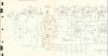
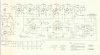
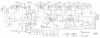
2. I found 2 different versions of the schematics online for this. I'm thinking that the "V2" of the attached files is the "correct" version, but if anyone is familiar with this, let me know.
3. Can anyone show me in the attached schematic exactly where I would put a CL-90 thermistor? (assuming an inrush current limiter isn't already present) The version of the schematic shouldn't matter for this question because that portion of both sets is the same.
4. Also, can anyone recommend a silicon rectifier for me (again, assuming that one hasn't already been put in). I know it will need to go following the rectifier in series with a 100 ohm 5w resistor to drop the voltage.
5. Should I plan on replacing all of the mylar caps on the parts list? test them first? do the PIO caps really make that much of a difference? They aren't crazy expensive from tube depot, so I'm not opposed to it.
 

Attachments

  • Fisher FM_100_B parts list.pdf
    Fisher FM_100_B parts list.pdf
    640 KB · Views: 14
  • FM_100_B schematics version 1.png
    FM_100_B schematics version 1.png
    179.9 KB · Views: 36
  • FM_100B schematics v2 p1.JPG
    FM_100B schematics v2 p1.JPG
    55.6 KB · Views: 37
  • FM_100B schematics v2 p2.JPG
    FM_100B schematics v2 p2.JPG
    64.5 KB · Views: 35
  • 20190826_083223.jpg
    20190826_083223.jpg
    48.1 KB · Views: 38
Register to hide this ad
I see this is not your first post on AK -- but one of your first, so welcome!

Before getting to any restoration efforts, addressing the low audio output would be the first order of business so that nothing done for restorative purposes could impact (good or bad) the current audio problem.

In addressing that, start by checking the 12AX7 tube located back by the audio output jacks to make sure it is good, the socket is clean, and the tube is properly seated in its socket. If that is all good, then check the voltages on each terminal against the schematic -- any schematic for the FM-100B -- as the wiring for this tube is basically the same between all models.

To get the proper schematic for your unit, determine your unit's serial number. The various service manuals offered by Fisher have the serial number range they serve on the front of the manual to help you get the right one for the version you have.

One other thing to check: As your tuner moves in and out of stereo lock (Stereo Beacon on or off), do you hear a clicking under the chassis?

Also, here is a thread I did on the FM-100B over four years ago now that you might find helpful.

https://www.audiokarma.org/forums/i...00b-fishers-best-bang-for-the-fm-buck.645489/

Let us know!

Dave
 
I see this is not your first post on AK -- but one of your first, so welcome!

Before getting to any restoration efforts, addressing the low audio output would be the first order of business so that nothing done for restorative purposes could impact (good or bad) the current audio problem.

In addressing that, start by checking the 12AX7 tube located back by the audio output jacks to make sure it is good, the socket is clean, and the tube is properly seated in its socket. If that is all good, then check the voltages on each terminal against the schematic -- any schematic for the FM-100B -- as the wiring for this tube is basically the same between all models.

To get the proper schematic for your unit, determine your unit's serial number. The various service manuals offered by Fisher have the serial number range they serve on the front of the manual to help you get the right one for the version you have.

One other thing to check: As your tuner moves in and out of stereo lock (Stereo Beacon on or off), do you hear a clicking under the chassis?

Also, here is a thread I did on the FM-100B over four years ago now that you might find helpful.

https://www.audiokarma.org/forums/i...00b-fishers-best-bang-for-the-fm-buck.645489/

Let us know!

Dave
Dave, I was hoping you would reply, as I have studied many of your threads on various Fisher units including the one you've linked me to above. It's the basis for most of the checks and mods that I have planned). Your writing is excellent; generally very clear, concise, and ALWAYS helpful, never judgmental or discouraging. While I will probably never be an "expert", I DO know when I am learning from one.

I'll check the 12ax7 as suggested, and will check voltages. I'm sure if I had stared at the service manuals long enough, I would have put 2 and 2 together on the serial number thing, but GOOD TIP, just the same!
Regarding the stereo lock: yes, I hear it click on and off.

Hopefully I'll be able to get to the FM-100-B this weekend and report back. First order of business, though, will be figuring out how I lost the left channel on the X100-B last night. I will probably be posting questions if I can't find answers on here already. It has been working quite nicely since I had it restored about 2 months ago. My dad (the original owner) and I had a nice listening session Tuesday night and then yesterday (Wednesday) I turned it on, dropped the needle on a Milt Jackson record, and got sound only out of the right channel. all tubes appear to be working, it's not related to the input, and I verified that it isn't an issue with the speakers, cables or source itself. I'll be trying swapping tubes around in the preamp section, switching the pairs of output tubes, and will visually inspect for any flared/burned resistors. after that, I'll probably come back here and go digging for info.
 
Last edited:
Thank-you for the kind words!

With your tuner, there is a good possibility that yours is an early version unit since you indicate you can hear a relay clicking as the unit moves in and out of stereo mode. Both the early and later versions use a relay for the stereo switching, but the early models use a larger more complex 3PDT relay (which is louder) to control both the Stereo Beacon lamp, and the actual switching of the audio circuits -- and that makes the relay the next place to look if the previous efforts don't resolve the issue. Those models with the audio switched by the relay contacts are often prone to losing one or both channels if the contacts on the relay become compromised -- which they do fairly often -- as there is no micro-arcing action to clean the contacts when the relay changes state. Fisher quickly became aware of this and tried various improved relays to eliminate the problem -- one that even used magnetized contacts -- but none really resolved the issue. They finally solved the problem completely by going to a diode matrix switching circuit that was controlled by a simple (much smaller and quieter) SPST relay, whose contacts were always passing current, which eliminated the relay contact problem permanently.

My own FM-200B had the audio circuits switched by the bigger relay, and cleaning those contacts became such a nuisance that I finally installed the diode matrix switching system in it which again, completely solved the problem. Some of the old audio switching relays worked pretty well -- but others like mine just always seemed problematic. So, if your unit uses the bigger relay, include cleaning those in your areas to check as well.

Let us know!

Dave
 
Thank-you for the kind words!

With your tuner, there is a good possibility that yours is an early version unit since you indicate you can hear a relay clicking as the unit moves in and out of stereo mode. Both the early and later versions use a relay for the stereo switching, but the early models use a larger more complex 3PDT relay (which is louder) to control both the Stereo Beacon lamp, and the actual switching of the audio circuits -- and that makes the relay the next place to look if the previous efforts don't resolve the issue. Those models with the audio switched by the relay contacts are often prone to losing one or both channels if the contacts on the relay become compromised -- which they do fairly often -- as there is no micro-arcing action to clean the contacts when the relay changes state. Fisher quickly became aware of this and tried various improved relays to eliminate the problem -- one that even used magnetized contacts -- but none really resolved the issue. They finally solved the problem completely by going to a diode matrix switching circuit that was controlled by a simple (much smaller and quieter) SPST relay, whose contacts were always passing current, which eliminated the relay contact problem permanently.

My own FM-200B had the audio circuits switched by the bigger relay, and cleaning those contacts became such a nuisance that I finally installed the diode matrix switching system in it which again, completely solved the problem. Some of the old audio switching relays worked pretty well -- but others like mine just always seemed problematic. So, if your unit uses the bigger relay, include cleaning those in your areas to check as well.

Let us know!

Dave
I have a bit more knowledge now, so am better equipped to ask for assistance. My serial number is 42xxx so it's a unit that follows the schematics most popularly available, and I have a corect set.
While there has been SOME work done (not all tubes are original) I believe I may have been a bit optimistic with my initial description. The unit is extremely clean inside, but appears unmodified, and honestly, it could very possibly be nearly unused. The rectifier has not been replaced, nor have any of the caps (that I can tell... if they were, they were replaced with original equipment) other than possibly the can cap, but that is not measuring 40uF on any of the sections (100uF, 101uF, 48uF, 90uF) so that will need to go. Basically, this needs a complete overhaul.

Now that I know what I am working with, I'd like to get it back up to original spec and perform reliability mods before taking on some of the mods discussed in your excellent write up on the FM-100B. In the interest of getting back to factory spec and adding reliability:
1. Is a CL-90 appropriate for this application? Where does it go in the circuit? Based on observations of others' work, I believe it should go on the AC inline that goes into the transformer. Basically immediately after the AC enters the chassis.
2. Can you suggest a replacement silicon rectifier bridge? And/or explain how it should be wired in? Most of the rectifier bridges I am seeing have only 4 contact points (the two for AC and then the + and - outputs) so I'm not sure if the "extra" negative lead coming off the existing selenium rectifier is just dropped (the two negatives are bridged on the selenium rectifier, anyway), or what? Also, I know I need a 100ohm 5W resistor goes after the rectifier and before the first filter cap. That would be on the positive output from the rectifier, correct? (I can't identify where it is on the picture in your 'Best Bang for the Buck' post)
3. Basically all of the 0.1uF mylar caps in my unit appear to be out of spec, so I'm just planning on replacing all of those. Should I replace with mylar or are film caps suitable here? PIO? I live quite close to Parts Express, so will likely source as many of the necessary parts as I can from there, unless there is a good reason to get parts which they do not carry. They do not carry PIO or mylar.
4. Since I'll be replacing the power supply caps, I know a replacement 4 section can cap is available from AES, but it is $40+ shipping. Standard electrolytic caps are pocket change, so I'm wondering if it would be suitable to just use 47uF caps, or 33uF (with or without parallel caps to bring total capacitance up to 40uF) I know that I have
5. Somewhere along the lines I read that C50 and C55 should be replaced by 5000pF caps. I can't find where I got that from, though. Does that modification make sense, in your experience and if so, where can I find 0.005uF caps?
6. I generally try to replace electrolytic caps with film (except power supply caps, due to physical size). The location of C65 (8uF) makes that pretty much impossible, and there are exceptionally few 8uF film caps available (Dayton Audio/Parts Express only sells one - and Audiocap Theta for $57... ouch!). Do you know of a suitable non-electrolytic cap for this application? or is a nonpolar electrolytic the best option? polar electrolytic? OE spec is a polar electrolytic.
7. While we're on the topic of capacitors, there don't appear to be readily available 0.5uF capacitors, but 0.47uF is quite common. Is that a suitable replacement? It seems like it would be since it is probably within the OE tolerance spec.
8. Generally speaking, is there an issue with replacing polar electrolytics with nonpolar film caps?
9. The large green glass 3w resistors (R17 and R19) are measuring 260ohm and 250ohm vs the listed spec of 270ohms. While I realize that is probably within the OE tolerance spec, and these are on the power supply so shouldn't dramatically impact sound quality, I'm wondering if I should just go ahead and change them out for some closer value resistors. They are easy to get to. Resistors are cheap.
10. Deoxit? and if so, which version?? Some other CRC contact cleaner? I know some electronics cleaners are NOT suitable for use on tube amplifiers because they leave a very slightly conductive film after they dry, and that other cleaners can damage plastics in the switches and pots. What is the best applicator? spray? brush? other? I don't want to screw anything up in here while trying to clean.

while my primary objective at the moment is to regain stock functionality, your recommendations on the multiplex unit have not been overlooked. I anticipate the overwhelming bulk of my listening coming from the stereo broadcasts from 91.7 FM (WVXU - this is the Jazz OT station) and 90.9 FM (WGUC - this is the classical station). Given that, I plan to install the tightest tolerance C225/C226 caps that I can find, and replace R222/R223 with 18k resistors. On that:
11. I don't have a 47k resistor showing in my schematic, and because (full disclosure) I am not knowledgeable enough to actually follow the details of the explanation provided in your post, I don't know how I will ensure that I drop my time constant down to ~70ms by changing that out. I do have a 4.7k resistor, but I suspect you're too good to have made an order of magnitude mistake like that. Perhaps this is moot, though (see 13, below) because it appears that might only affect the mono network?
12. Should I hold off on doing all that until I perform the other updates? Should I hold off until I can actually test the frequency response? Do I need an FM signal generator to test the frequency response, because if so, that's beyond the tools I have, presently.
13. Since I don't plan to do much (if any) mono listening, is there any reason for me to modify the mono network at all?

I can't thank you enough for the input you have given on this, and my X-100-B projects. I only hope that sharing that knowledge brings as much joy to you as learning it does to all of us, and that the knowledge you possess can be memorialized here and elsewhere for the use of all future generations. I look forward to reading your reply.
 
I'll try to answer your numbered items as best I can. Others are free to contradict me as I am not an expert, but I will share what I have learned. I recently refurb'd a Fisher KM-60 tuner that originally came as a kit which is similar in some respects to the FM100-B.

1. A CL-90 is correct for the current draw of the tuner.
2. I used a 3A 600V bridge. The 3A is more than enough. Mouser part 583-BR36. If you want to use DK you can find something with similar specs. You only need four connection points on the bridge - two for AC in and two for DC out. Assuming your unit has a selenium rectifier then yes, you need a dropping resistor. I found I needed a bigger one than 100 ohms because the tuners don't draw that much current - meaning the voltage drop for 100 ohms will be too small. You might have to do a bit of trial+error. I'm just saying....
3. Film caps will be fine. Just make sure the voltage rating is at least as big as the originals. In terms of which ones are better, well I'll leave that to others.
4. 47uF is fine in the power supply to replace 40uF caps. Just make sure the voltage rating is at least as good as the originals. For my KM-60 I used the AES multi cap though and I wasn't worried about the one-time $40+ cost. It's a classic and if done right your tuner will last for decades.
5. In general for caps I look at the parts list in the service manual and try to match up the type unless I know they are in the audio path (not RF or IF path). If in the audio path I try to use film caps even if it came with electrolytic caps.
6. <same as previous>
7. The 0.47uF is within 10% tolerance of 0.50uF. That's fine and probably as close as you can get.
8. Replacing electrolytic with film caps with similar voltage ratings mean bigger size and bigger price. The film might last longer. Personally I don't do that unless it is in the audio path.
9. Change the 270 3W resistors if you want or leave them - they are still reasonably in tolerance. Personally, I'd measure the voltage across them (if you can safely power it up at this point) and calculate the power dissipation to see if you need to bump to 5W or if 3W is ok. Sometimes Fisher ran the higher wattage resistors close to limits - sometimes not. Are they discolored at all?
10. I use Deoxit on everything except for pots. Some say that Deoxit isn't good for the carbon traces on pots. For pots I use fader lube.
11. <I'll leave the time constant question to the experts.>
12. Hold off on what? Not sure what is the question, but any fancy equipment I would think about would be to do a real alignment, but I don't have that kind of equipment and I don't have the skills. I do note that my KM-60 was designed for user alignment without special tools to be done by the builder. I ran the instructions that it came with and the alignment appears to be pretty good. I don't think your FM100-B has that option, but others can chime in.
13. Not sure about your reference to the mono network, but the front end is always mono - even in new Stereo tuners you can buy today. That mono signal from the front end is eventually sent to the multiplexer and is then split into the right and left stereo signal if you have selected "stereo" on the front panel. You will still want to make sure the mono portion is good because you don't have separate circuits for mono vs. stereo excepting for the previously mentioned multiplexer.

I hope this helps and I hope my assistance isn't found to be incorrect, but lets see what the real experts say.
 
Last edited:
Further regarding Item #3 about replacing any selenium rectifier, I found my post #103 in the following thread where I ended up using a 220 ohms dropping resistor to makeup for the loss of internal resistance when going to a silicon solution for my Fisher KM-60 tuner. I'm not saying you should go out and buy this resistor as you'll have to see how much drop your unit will need first, but assuming you have a selenium bridge to replace, I would go with 5W for whatever you end up with, but if you are needing to drop 10V then real power dissipation for a 220 ohm resistor is: V*V/R = 10*10/220 ~ 1/2W, if you know what I mean. (It's cool if you don't know what I mean. Just trying to say what I'd do.)

https://audiokarma.org/forums/index...nd-rusty-the-fisher-km-60-tuner.821273/page-6
 
Further regarding Item #3 about replacing any selenium rectifier, I found my post #103 in the following thread where I ended up using a 220 ohms dropping resistor to makeup for the loss of internal resistance when going to a silicon solution for my Fisher KM-60 tuner. I'm not saying you should go out and buy this resistor as you'll have to see how much drop your unit will need first, but assuming you have a selenium bridge to replace, I would go with 5W for whatever you end up with, but if you are needing to drop 10V then real power dissipation for a 220 ohm resistor is: V*V/R = 10*10/220 ~ 1/2W, if you know what I mean. (It's cool if you don't know what I mean. Just trying to say what I'd do.)

https://audiokarma.org/forums/index...nd-rusty-the-fisher-km-60-tuner.821273/page-6
Tim, thanks for the good info!
I've bought most of the parts I need between digikey and parts express. I'm going to check dimensions before ordering the can cap and a few other things from AES.

2. I guess I am looking for a resistor that yields 195V after the resistor, eh? Is there a way I can quickly and easily nail down the required resistance without needing to power on, power off, discharge caps, unsolder, re-solder, bring it up on the variac, etc each time? I can get a handfull of different value 1w resistors between 100ohm and 250ohm
5. I figure as long as the specs are the same or better (i.e. tighter tolerance, higher voltage rating) I'm not going to do harm by going from electrolytic or mylar to film and foil.
9. is there any reason not to just go with a 5W, and "overbuild" it? (or my penchant for way over-spec design jsut a carryover from my civil engineering background...)
10. Are you partial to any particular formula of the Deoxit? I have heard that some are better than others in various applications, but I don't recall there being broad consensus other than that it is somewhat application specific. And good tip on the fader lube. I hadn't heard of that before. Will get some!
11. I was referring to holding off on modifying the multiplex unit based on Dave G's recommendations in his piece on the FM-100B.
As for the alignment, I assumed that unless someone on here has brilliant ideas about how to do it myself, I'd be taking it to a specialty shop for that, hopefully somewhere in town (cincinnati). If I can get the alignment done for an hour's labor or so, I should have a fully restored, exceptional tuner for around 3 bills, which is a steal, in my book.

Hopefully Mr. Gillespie can chime in with some pointers on the multiplexing and alignment questions... To preempt ONE question I expect he may have:
Yes, I have replaced the ECC83 in the multiplex unit. The one that was in there was a mullard, which I pulled so I could have twin mullards in the phono section of my X-100-B. A late 60s RCA resides in the multiplex unit now.
 
klamsoss,

Some comments for your numbered items in your previous post.

2. So the tricky part is knowing how much current your system will draw at the DC voltage level you are measuring. I measured the current by inserting an initial resistor (100 ohms) into the circuit and then used a multimeter to measure the voltage. You can use ohm's law to calculate the current. (Example: You measure 12VDC across the 100 ohm resistor, so the current draw is: 12VDC/100 ohm = 0.12A.) (Of course you do this after you have done enough to the tuner to make it safe to power up.) Then you need to know how many volts you "want" to drop. The resistor is then calculated based on ohm's law. Let's say you want to drop 20VDC and you know the current draw in that part of the circuit is 0.12A. Your resistor would be 20VDC/0.12A ~ 170ohms. Confusing? Sorry if it is.... EDIT: See Dave's corrections in post #14 below.
5. No you won't do harm to the circuit to replace electrolytics with film caps. The only harm is to your wallet. Film caps are typically larger. Sometimes a lot larger. Typically electrolytics have a lifespan to them whereas film caps usually don't. That is a benefit for the extra cost and size. Film caps can sound better when they are in the audio path. Maybe there are other benefits to film caps that I'm missing such as value stability over long periods of time, etc.... Maybe less likely to drift? Probably.
9. Sure, you can overbuild it. Just check pricing and pick a resistor with at least 2x or 3x of the actual dissipation. I mentioned 5W because there are usually a good selection of values at that dissipation.
10. I use Deoxit D5, but I'm no expert on Deoxit. Maybe others will chime in.
11. Got it. You were talking about the Multiplexer. I think there is one easy to reach electrolytic in the multiplexer. My multiplexer was a "WX" variety and I was told that changing that cap didn't change the multiplexer alignment. I changed that cap in mine and it didn't cause any problems, but that was the only part I touched in the multiplexer. The general consensus for the multiplexer seems to be that if it ain't broke......

I can't speak to the alignment because if I had an FM100-B, I would probably find an expert to do the work. I don't have the tools or skills. I was lucky with my Fisher KM-60 as it was sold as a kit and was designed to allow a lay-person to do a decent alignment with the built-in signal meter and some plastic IF core tools. There is a switch on the chassis of the KM-60 that allows the builder to change the purpose of the meter for this activity. I did the alignment as instructed in the KM-60 Service Manual and I'm happy with the result. I don't know if any other Fishers have that capability. Maybe the experts could chime in.

Dave is the professor around here, so my inputs are worth about 2 grams and his inputs are worth about 2 tons! I learned most of what I'm sharing from others (including from Professor Dave.)
 
Last edited:
Tim, thank you!!!
Not confusing!!! I'm familiar with ohm's law, but I know this thread will help some enterprising reader in the future. And you've answered a few other indirect questions I would have had (After caps, thermistor, and new resistors are in, will I damage anything by powering up for a couple minutes to measure current/voltage?... sounds like the answer is no).
Re: cap choice
I have done a bunch of crossovers. I have 33uF film caps on the bench now, so I know, they're HUGE. The 8uF is going to be an electrolytic but the others, I think dayton makes sufficiently small film caps to substitute.
The 1uF in the multiplex is becoming a 1% film cap.
I've got some D5 on order now.
And yes, Mr. G is frankly brilliant. His awareness, familiarity, and general level of comfort with Avery's designs and circuits in general is, on inspection, genius. You dont have to understand it all to see that much. His posts have been a guidebook for me, and any of them that I know of are bookmarked.
 
klamsoss,

Sounds like you are on your way. Just make sure that any caps you install have the same or higher voltage rating.

If you've updated the power supply and misc electrolytics and done some basic checking then you could bring it up on a variac or dim bulb tester (DBT) to check it out. When you are confident that it's healthy then you can put it on line voltage and take your measurements.

Good luck.
 
Last edited:
De-Oxit D5 is the cleaner (which most pots need desperately), while Faderlube (F-5) is formulated as a Slider Lubricant. With the Cost of De-Oxit and Faderlube, a little bit does a lot. Having said that, Faderlube is not really the correct formulation for pots. GOLD or SHIELD has a higher content of lubricant and would be a better choice for pots. But to get the best results, use the D-5 and the (F-5, G-5 or S-5) as a one-two punch. You clean the environmental contaminents off the tracks, then lubricate them. I've stopped using F-5/G-5/and S-5, as they are prohibitably Expensive. CRC 626 electronics lubricant works just as well in place of the (F-5/G5/S5) Caig products for lubrication. And you can get a can @ Home Depot for about $6 and change.
 
De-Oxit D5 is the cleaner (which most pots need desperately), while Faderlube (F-5) is formulated as a Slider Lubricant. With the Cost of De-Oxit and Faderlube, a little bit does a lot. Having said that, Faderlube is not really the correct formulation for pots. GOLD or SHIELD has a higher content of lubricant and would be a better choice for pots. But to get the best results, use the D-5 and the (F-5, G-5 or S-5) as a one-two punch. You clean the environmental contaminents off the tracks, then lubricate them. I've stopped using F-5/G-5/and S-5, as they are prohibitably Expensive. CRC 626 electronics lubricant works just as well in place of the (F-5/G5/S5) Caig products for lubrication. And you can get a can @ Home Depot for about $6 and change.
Good stuff, Larry. I have never run across a practical explanation of the different formulas. Thank you!!!
 
Great discussions! One thing I would add is that when you add a resistor after the new silicon rectifier -- but before the first filter cap, then basic Ohms Law does not work. Oh, it works in modified form, but not in the conventional manner. That's because the resistor is dropping not only a DC voltage, but also and AC voltage that represents the ripple current drawn by the first filter cap.

In the example given, a 20 volt drop was needed with a load current draw of .12 A, requiring a dropping resistor of 167Ω, and producing a dissipation of 2.4 watts. That's true for the DC component of the voltage drop across the resistor. But a 2.4 watt resistor would burn up in this application, as besides the DC voltage drop of 20 volts, there will also be an AC voltage drop of about 15 volts that must also be accounted for dissipation wise. The AC voltage drop adds an additional 1.35 watts of heat being dissipated through the resistor, on top of the 2.4 watts developed from the DC component. Therefore, in this type of application, the actual dissipation is on the order of 3.75 watts, or 156% of what just the DC voltage drop would indicate the dissipation to be.

Because of the AC and DC voltage drop through the resistor, the value for a resistor used in this type of application is best determined through experimentation. Once that value is determined however, the true dissipation is determined by adding both the AC dissipation and the DC dissipation together, and then choosing an appropriate wattage resistor from those results.

One other point to add: The resistor should be determined under the conditions of no antenna connected, and the tuning pointer turned all the way to the left of the dial. Under these conditions, the tuner circuits draw the most current, and are the conditions that the schematic indicated voltages represent. It will be found that when a station is tuned in, all B+ voltages in the tuner will rise notably, as a received signal generates bias voltages that typically reduce the current draw of RF and IF amplifier stages, causing the voltage levels to rise.

Dave
 
Great discussions! One thing I would add is that when you add a resistor after the new silicon rectifier -- but before the first filter cap, then basic Ohms Law does not work. Oh, it works in modified form, but not in the conventional manner. That's because the resistor is dropping not only a DC voltage, but also and AC voltage that represents the ripple current drawn by the first filter cap.

In the example given, a 20 volt drop was needed with a load current draw of .12 A, requiring a dropping resistor of 167Ω, and producing a dissipation of 2.4 watts. That's true for the DC component of the voltage drop across the resistor. But a 2.4 watt resistor would burn up in this application, as besides the DC voltage drop of 20 volts, there will also be an AC voltage drop of about 15 volts that must also be accounted for dissipation wise. The AC voltage drop adds an additional 1.35 watts of heat being dissipated through the resistor, on top of the 2.4 watts developed from the DC component. Therefore, in this type of application, the actual dissipation is on the order of 3.75 watts, or 156% of what just the DC voltage drop would indicate the dissipation to be.

Because of the AC and DC voltage drop through the resistor, the value for a resistor used in this type of application is best determined through experimentation. Once that value is determined however, the true dissipation is determined by adding both the AC dissipation and the DC dissipation together, and then choosing an appropriate wattage resistor from those results.

One other point to add: The resistor should be determined under the conditions of no antenna connected, and the tuning pointer turned all the way to the left of the dial. Under these conditions, the tuner circuits draw the most current, and are the conditions that the schematic indicated voltages represent. It will be found that when a station is tuned in, all B+ voltages in the tuner will rise notably, as a received signal generates bias voltages that typically reduce the current draw of RF and IF amplifier stages, causing the voltage levels to rise.

Dave
This might be a dumb question but how do I determine the above-described AC voltage drop?
I have an assortment of 7 and 10 watt resistors and will just use one of those with the appropriate resistance, but this is something I expect I will want to know for future projects.
 
Okay, folks....
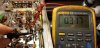
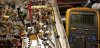
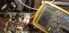
I just replaced a couple of the out-of-spec mylar caps. Once in the FM-100-B chassis, they test way off! The new 0.1 uF capacitors are rated for 250V, tolerance of 1% (usually I use these in crossovers) and all test within spec out of the bag.
This is C45 and should be 0.1 uF
20190918_000926.jpg
This is C36 and should also be 0.1 uF. 20190918_001032.jpg
I don't understand why this would happen.
I doubt my DMM is wrong since it accurately reads values of new passive components, and it also reads other capacitors accurately in-circuit. For example, here is the 600V 0.01uF power supply bypass cap, and it's pretty much spot on.
20190918_001300.jpg
Is there a simple explanation for this? Might I have damaged the caps during installation by overheating them? That hasn't happened to me in the past in any similar situations...

Side question:
What kind of flux are you guys using? The weak-ass crap I have right now just makes a mess and runs everywhere.
 
The value of the resistor is sized to produce the correct DC voltages under the conditions mentioned. In calculating the wattage dissipated, use the DC voltage drop across the resistor, and the resistor's value to determine the heat dissipation due to the DC component. Then measure the AC voltage drop across the resistor and determine the the heat dissipation due to the AC component. Add the two dissipation values together, and that is the true heat dissipation being dissipated by the resistor. Knowing that, you can then install an appropriately rated resistor accordingly.

Dave
 
It's always best to remove (or lift one lead of) a component for testing, as when installed, sneak circuits can influence the reading displayed by your tester. In some circuits where sneak circuits don't exist, then an in circuit indication will be accurate, but with others where they do exist, it will not. Your tester has no way to distinguish between the two conditions.

Dave
 
Phew! Okay that makes more sense.

In light of this understanding, I wonder if my original assessment of the mylar caps is correct. Perhaps they weren't bad, after all.

Thank you for the tip on the AC and DC voltage drops. As I said way up top, I'm new to this so never would have thought to check for both AC AND DC voltage after the rectifier.
 
Last edited:
It's only important when a resistor is used between the output of the rectifier and the first filter cap. When there is a cap connected directly to the output of the rectifier, then the AC component can be basically disregarded in determining dissipation watts for the first dropping resistor encountered after it.

Dave
 
Back
Top Bottom