• The move to the new server is done. There are some software and database maintenance updates in process. This has us passing the hat around to help out. We appreciate any donations. Seriously, even a dollar helps. The payment page may be found here - https://www.audiokarma.org/support.html

Fisher FM-100-B issues

Does it matter where I ground the power section caps? I ended up NOT going the replacement can route and am employing Nichicon 39uF electrolytics of appropriate voltage (plus 1uF 450V film bypass caps). Fitting them in neatly may require grounding one or more of them to the same lug and/or to lugs where other passive components are grounded.

My intuition tells me that a ground is a ground is a ground, but you guys know vastly more than me, and there may be some nuance that I'm unaware of.
 
I always use the same ground of the power cap I'm replacing. Never had a hum issue or ground loop problem doing it that way.
 
I always use the same ground of the power cap I'm replacing. Never had a hum issue or ground loop problem doing it that way.
Thanks, bhamham. I intended to do that, but one of the tabs for the OE can cap is solid... no lug hole, and I haven't been able to melt the chassis solder on that tab, either, to bury a ground there.
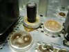
Originally I was going to replace or stuff the can with 3 of the 4 capacitors, but at 890 degrees, as high as I can set my iron, I couldn't melt the chassis solder for 2 of the tabs. That's how I arrived at NOT replacing the can. 20190921_225037.jpg
So I'm down one ground point.
There IS one existing, vacant ground lug on a nearby soldering lug strip. 20190921_230515.jpg
I plan to use that unless one of you professors here has a good reason not to.

I'll take this chance to update what I have done:
20190921_231102.jpg
CL-90 on the incoming AC line. I'm not sure I have it on the right side, though but I understand it's okay to have one on EACH, so that's what I will be doing.
Selenium rectifier swapped for silicon bridge rectifier. I will have a 10w 100ohm dropper alligator clipped in line before the first power section capacitor, per the previous discussion about determining the appropriate resistor there.
Also replaced the power section bypass cap 0.01uF 600V

See next for further work completed this far.
 
I replaced the electrolytic capacitors in the rest of the amp, and at least one actually out of spec mylar cap, plus 2 or 3 that weren't actually out of spec. Then 8uF remains electrolytic due to practical space considerations.
I also replaced the 1uF electrolytic cap in the MPX section with a solen film cap. And the 2200pF caps with high accuracy units. (Not pictured)
 

Attachments

  • 20190921_232015.jpg
    20190921_232015.jpg
    60.8 KB · Views: 9
Yea, those solder joints on those old cans are a real pain. I use a cheap stain glass iron to get to them. However, now I just cut the bases off the old can and leave them on the chassis with all the wires and components attached. Then empty out the old cans and stuff them. I drill a hole in the base and feed my wires through it, soldering the new cap leads to the original lugs, and glue the cans to the old bases.
 
Yea, those solder joints on those old cans are a real pain. I use a cheap stain glass iron to get to them. However, now I just cut the bases off the old can and leave them on the chassis with all the wires and components attached. Then empty out the old cans and stuff them. I drill a hole in the base and feed my wires through it, soldering the new cap leads to the original lugs, and glue the cans to the old bases.
Do you have a picture? I'm having trouble imagining where the cut on the can would be.
 
Woah crazy! I have never seen the inside of a can cap before. I guess I'm not sure what I expected it to look like, though. Good stuff!
 
Okay, power section finished, all the electrolytic capacitors have been replaced, I've made the recommended adjustments to the timing constant, and to the MPX section, selenium rectifier replaced, 100 ohm 10w dropping resistor temporarily in line(until I calculate the actual resistance required) power bypass cap replaced, current limiter added... I think that covers all the work I've done.
As I power this thing up for the first time, using an autotransformer, what should I be looking for and/or measuring?
I have 2 voltmeter so can set one to monitor actual voltage... what else? and how long should I be taking to bring it up to 120VAC?

Obviously once it is up to full power I can measure test points and check tube voltages are within spec. And calculate the necessary value for the dropping resistor.
 
Last edited:
I'd monitor the B+ at the first filter cap, and the heater voltage powering the RF/IF tubes (one side of which will be grounded). Bring the heater voltage up to about 6.4 vac at the furthest point in the heater string. Then with no antenna attached and the tuning knob turned all the way to the left (lowest frequency), adjust the first filter cap voltage to the correct value with the new resistor added between it, and the output of the new bridge rectifier. You should be able to bring the voltage up rather quickly, say in a minute or less.

Dave
 
I'd monitor the B+ at the first filter cap, and the heater voltage powering the RF/IF tubes (one side of which will be grounded). Bring the heater voltage up to about 6.4 vac at the furthest point in the heater string. Then with no antenna attached and the tuning knob turned all the way to the left (lowest frequency), adjust the first filter cap voltage to the correct value with the new resistor added between it, and the output of the new bridge rectifier. You should be able to bring the voltage up rather quickly, say in a minute or less.

Dave
Well, I have another mystery for you guys, now.
2 days ago upon completing the above detailed work, I plugged in my variable autotransformer, plugged the Fisher unit into that, and brought it up to 70-80% power. All the tubes began to glow, the dial indicator lamp lit up and everything seemed to be fine. I didn't know what to measure, though, so I powered down after no more than perhaps 2 minutes max.
I returned to it today, set up my meters as Dave suggested, and attempted to bring my FM-100B back to life. Upon powering up, neither meter registered anything more than a few mV. While trying to figure this mystery out, I saw a small amount of smoke which appeared to come from the vicinity of the droping resistor and/or the insulation on the jumper wires I used, which were in contact with the resistor, and became aware that the 100ohm dropping resistor (10w) I put in place temporarily was getting EXTREMELY hot. I powered down again, looked over my work leading to the first filter cap, and on the power section in general. Unable to identify any mistaken grounds or missed connections, I tried the unit again at a lower voltage on the variac. This time, I got nothing. The resistor doesn't get hot. The tubes don't light. the dial light bulb doesn't come on.

I assume that the hot resistor was the result of a lot of current flowing, but I don't understand why I would get essentially no voltage (peaked at 0.2V) at the first filter cap if there was current flowing. I also don't understand why things would have lit up the first and second attempts, but the volt meter registered no meaningful amount of voltage.

At 85V A/C being fed to the unit, I get 25 Volts A/C at each black lead from the transformer. I assumed this meant the fuse had not been blown, thought I didn't actually check the fuse (I will tonight). The red wires yield around 325mV A/C, essentially nothing. Is there a way to check the transformer? Could I have blown up my rectifier? My power caps are grounded to lugs on terminal strips that I attached to the chassis with steel machine screws and nuts. I didn't solder them. Could that be the issue?

I have a sinking feeling that I something wrong and caused excess current which blew the previously perfectly fine transformer.
As always, any help or advice you have is appreciated.
 
Last edited:
Great news! Sort of.... it turns out it WAS the fuse. That doesn't explain why there was no voltage before it blew, though. I also can't figure out what I did wrong to cause the fuse to blow.
On the plus side, I have my Mighty Mite II up and running, and will have it calibrated by this weekend. So, all the FM-100-B tubes will get looked at. Can a bad tube cause the condition I ran into and for a fuse to blow in that way?
 
Sounds more like you mis wired something during rehab. Possibly one of the caps in the P.S. as the 100Ω power resistor is taking a beating. Check polarity on all the caps (possibly backwards). Tube is doubtful on the tuner to cause the fuse to blow unless it's a cascading failure and it doesn't sound like that from what I've been reading on your posts. .
 
I will review all of my replacement caps. I'm 90% sure I didn't reverse anything, but I'll carefully recheck, and make sure there isn't an inadvertent ground somewhere that I am missing.
Quick side question: will any 1 amp fuse work as a replacement (I have a handful of various fuses. I'm sure there is a 1A in there somewhere) or is there a specific type you guys recommend?
 
Greetings all, and apologies for my long absence. I've had a busy couple months of racing, and moving, but I'm back to working on my stereo gear, including this Fisher FM-100-B.

I couldn't identify the issue that was blowing fuses but I reasoned that it must be in the power supply since I wasn't getting anything after that. So, I just started taking the power supply apart and then reassembled it. I'm annoyed that I couldn't identify any issue during deconstruction, but after rebuilding, the unit seems to sustain B+ of 195 V dc (spec listed in the SM) at the first supply cap for several minutes without blowing the fuse. Therefore, I'm accepting progress and moving on to the next stage. I believe that next stage is identifying the proper value for the dropping resistor that will yield a B+ of 195 V DC before the first power supply cap, and also yield 6.3-6.4 VAC at the end of the heater string when this is plugged in to my normal wall voltage. BUT I have another neophyte question:

Is it likely/possible that a dropping resistor which yields B+ of 195 V would result in a heater voltage that is way off?
Or would I expect that a properly tuned B+ voltage would yield an appropriate heater voltage (and if it did NOT, that is an indication of other problems being present)?

I understand how to calculate the power handling need of the resistor (thanks Dave, and Tim!), although I have a bunch of 10 watt cement resistors on hand and will most likely just use one of those despite it almost certainly being overkill. Regardless, I need to determine the right resistance.

Separately, I have now tested all of the tubes and two of the 6AU6 tubes tested positive for short on my (newly restored, by me) Sencore Mighty Mite II tester. So, it looks like I'm going to have to find someone to do an alignment for me.

Many thanks!
 
Last edited:
Okay, guys, old problems resolved (a detailed explanation of the work I did is below), but now I have a new problem!

I fired this thing up Friday night after verifying that my B+, IF heaters VAC, and other tube pin voltages were, for the most part, pretty close to spec (with the exception of the MPX section, where things got weird*). The specified Test Points were off, and smaller magnitude voltages were off a bit (i.e. -2.2 V spec vs. -1.11 V measured), but I assume that when I have this aligned, it will bring these back to the right level. To my delight, I immediately started pulling in strong signal, including stereo switching. I listened for about 20-30 minutes and noted some muddiness across basically the whole audible range, and what sounded like some very low frequency rumble. So, sound quality not quite what I hoped for, but I think an alignment (planned for as soon as I resolve the other issue at hand) may clean most of that up. Distant and local switching seemed to work, too. Pleased with the success, I shut my system off and went to bed.
* I'll need to go re-check, document and report back the voltages in the MPX section. I couldn't make complete sense of them when testing after my initial resto, because some voltages were in spec while others were incredibly NOT. Stereo reception brought some of the NOT spec voltages in line but pushed others out. I'll report back.

I came back Saturday morning, turned the tuner on to have some classical accompaniment for my other projects, and after about 3 to 5 minutes, the right channel dropped. No pops, no clicks, not a slow fade-out, nothing dramatic. It just stopped putting out sound.
Not the amp, not cables, definitely the tuner.
Switching the tuner function from automatic to stereo to mono had no impact, nor did the level pots on the back resolve the issue. Turning the right channel output pot all the way down reveals there is SOME signal from the left side, but it's very quiet.
The same thing happened Sunday morning. 5ish minutes of good, stereo operation, then the right channel drops.
Obviously something is failing once the unit heats up. It seems odd that this didn't happen the first night when I tested it out, but it's consistent, now. I'm not even sure where to start, since all my tube pin voltages seemed to be pretty close to right (other than MPX).

Any ideas?


Quick recap of my FM-100-B journey thus far:
Picked up this unit over the summer, thinking it had seen some work and it turns out it was never touched, save for a few tubes having been replaced. I was getting no output on either side, and tube pin voltages were pretty much all out of whack all over the place. Can cap sections tested way off, so I figured I'd just go ahead and restore the whole thing.

1. Deoxit on all pots and switches, followed up by contact cleaner with lube. Sockets cleaned. Tested and found one shorted 6AU6 tube, and two more giving me inconsistent readings. I'm not sure if this is a problem with my tester, or with the tubes, but I went ahead and replaced all three with used-but-good Fisher branded tubes. Output and MPX 12ax7s tested fine, but I swapped them with a pair of good GE 12ax7s I had on hand to eliminate variables with the NEW problem.
2. CL-90 installed on one leg of the AC line, immediately before it hits the fuse, and I replaced the 0.01uF bypass capacitor (C10 in the diagram and parts list)
3. The selenium rectifier was replaced with a Vishay single phase 600V 3A silicon rectifier. And at wall voltage, a 100 ohm dropping resistor yields 198-199 VDC at the first filter cap (spec is 195), but subsequent B+ voltages are in line. I used a 10 watt I had on hand, so plenty of power handling.
4. I was going to use a replacement can from AES, but I couldn't de-solder the can cap form the chassis with my iron, and didn't understand "re-stuffing", at the time. I used 39uF 350V nichicon caps to replace the first two sections. The remaining two are 47uF (measured 45uF) 250V unknown brand from my local shop. I added a terminal strip to provide solder lugs, and 2 additional ground points to replace the terminals of the can cap. While I did this, the 270 ohm power section resistors (R17 and R19) were out of spec so were replaced. The 470 ohm R18 resistor was also replaced, due to damage during power supply work.

Next I did some signal path restoration and upgrading.
5. Mistakenly thought the mylar caps were bad and cut them out after testing them in-situ (they all test perfectly fine). Replaced with either Dayton polypro film caps, or k40y9/k42y2 PIO caps (for signal path) and include C36, C45, C49, C69, C71 and C72.
6. Other caps replaced:
  • C63 (2uF electrolytic ) - 2uF film
  • C65 (8uF electrolytic) - 8uF nichicon electrolytic
  • C70 (0.5uF electorlytic) - 0.47 uF film
  • C210 (1uF electorlytic) - 1uF film
  • **C225 and C226 (2200pF ceramic) - 2200pF high accuracy hand-matched ceramic, as part of de-emphasis network mod, on Dave G's advice.
7. Resistors (other than power section resistors) were replaced as follows:
  • **R222 and R223 (22k) - replaced with hand-matched 18k metal film resistors as part of the de-emphasis mod
  • R77 (47k) - replaced with 39k (actual resistor measured at 37.8k) as part of the timing constant adjustment mod. I chose this value after reading Larry's post regarding his own work on that section.
8. After all was said and done, I went back through with 90% isopropyl to clean up any flux that ran. (I plan to clean the chassis top itself using ammonia, and polish it up with Brasso. That combo worked well on my X-100-B)

Pictures to come.

 
Last edited:
If you are certain that the right channel drops out when set to mono mode ("Switching the tuner function from automatic to stereo to mono had no impact"), and, you are certain that the dropout is not due to the relay contacts discussed in post #4 (was it ever determined whether you have the version with an audio switching relay?), then the problem must be in the output amplifier section.

Dave
 
If you are certain that the right channel drops out when set to mono mode ("Switching the tuner function from automatic to stereo to mono had no impact"), and, you are certain that the dropout is not due to the relay contacts discussed in post #4 (was it ever determined whether you have the version with an audio switching relay?), then the problem must be in the output amplifier section.

Dave
Dave, as it turns out, switching to mono DOES result in equal output from both channels. I thought I had checked it, but clearly I was wrong.
As for the switching, see pictures. I believe I have the "old style", and not the matrix you updated your own FM-tuner to employ.

First pic is the switch, and the selector.
2nd pic is power supply and output areas.
3rd is the "front half" including the selector (again) and all other switches, as well as the MPX section. Which reminds me that I replaced C214 (0.0047uF) between pins 1 and 7 on the 12ax7 in the MPX section.
Last, the front/top view. This unit was very clean, but you can see the slight streaking on the chassis. Hoping some brasso metal polish will remove that tarnish.
 

Attachments

  • 20191216_214934[1].jpg
    20191216_214934[1].jpg
    84.7 KB · Views: 29
  • 20191216_215647[1].jpg
    20191216_215647[1].jpg
    50.2 KB · Views: 28
  • 20191216_215657[1].jpg
    20191216_215657[1].jpg
    51.4 KB · Views: 29
  • 20191216_213344[1].jpg
    20191216_213344[1].jpg
    48.9 KB · Views: 25
Back
Top Bottom