• The move to the new server is done. There are some software and database maintenance updates in process. This has us passing the hat around to help out. We appreciate any donations. Seriously, even a dollar helps. The payment page may be found here - https://www.audiokarma.org/support.html

Fisher SA-300B Set-up and Bias Adj. Question

Quick after-thought here: Any suggestions as to where you'd drill 6 holes for test points? Sacrilege, Blaspheme...what ever...... I'm of the belief that a minor change like that...the permits the proper function of the amp as designed to be monitored, adjusted, and maintained....that's an 'acceptable' change which would NOT have a detrimental affect on value of the amp. On the contrary.....it should enhance it. But, who knows....... I just know I think it's appropriate......and I think I'm going to try to do it. Just wondering if I should attempt to squeeze them into the top surface, or maybe 'side-mount' them on either the back or front? Just looking for your thoughts or suggestions. TSD
 
Well one thing's for sure, there are quite a few holes around those output tubes. I'd just be judicious about using them. They look appropriately sized for test point receptacles. Don't create hot spots.
 
What's wrong with just clamping the probes to the right resistor under the chassis and to the chassis itself instead of adding test points? I guess it depends on where the amp's going. If I were planning on selling it, I'd think twice about test points if drilling is involved. People are funny.

A few other thoughts:

1. Dave had trouble with the riveted ground terminations on his SA-100 update as I recall. It's worth checking all of them on this amp which is from the same era and also is of similar construction.

2. When my SA-300 red-plated a tube, I decided that I was done with EL-34 stuff until I had the time to study it properly. After all, both my X-1000 and my SA-300 had acted up, both when the AC voltage went over 125 volts here.
That decision was made before Dave restored my Fisher X-1000, which is an EL-34 based amp. My gut now tells me that what's documented in that X-1000 thread, including Dave's EFB circuit, would apply to this amp.
Researching that X-1000 thread will tell you a lot about this unit also. I'd suggest starting your reading on page 4.
http://www.audiokarma.org/forums/showthread.php?t=306741&highlight=X-1000&page=4

3. I have a note in my things to do to this SA-300 amp that says to add screen stability resistors.

4. The RCA input outer shield is at amp ground potential.

5. On the SA-300, there is a ground terminal and next to that a common terminal. On mine, I used the common terminal. The only thing separating the common and ground is a 0.47 ohm 5 watt resistor on each channel. That's an oddity. It's possible that the SA-300-B may have speaker common terminals that are not at ground potential to support the use of a summed center channel output. Dave has mentioned on the Fisher 400, X-1000, and X-101-C restoration threads that the speaker common not being at ground potential is an issue when testing.
 
Last edited:
What I would do is remove the single bias pot and split the circuit using 2 pots mounted on a small pcb with the necessary C +R. That small pcb with pots would be mounted on stand-offs on the same wall that contained the original bias pot. In this manner, the pots would be facing the removable side wall for adjustment.

Not sure about the test points yet-they could be mounted on the same pcb as the trimmer pots or I could fashion some "socket savers" with leads to plug into a couple of DMM's. The "socket savers" would have a 10 ohm resistor between the male and female cathode pins so I could measure voltage drop and calculate the current. Once the amp was running stable, I'd remove the "socket savers" and replace the tubes in the amp.

That seems like the least intrusive and easiest method to accomplish my goal. That removable side panel would give me access to 2 bias pots and the test points would come from the tubes themselves.
 
Audiodon,
Thanks for posting the picture of your amp. My amp was worked on by a hack before I got it and any image of an amp in pristine condition would help.
I'm not sure, but I think the original bias supply rectifier was selenium. Your amp appears to have a silicon diode in its place. I'm not certain, but I think the guy who worked on my amp may have used a Zener Diode. I also noted one different component value. Where there were originally two 15 ohm power resistors in series, one has been replaced with a 16 ohm resistor. I'm not sure if he did this to compensate for today's higher line voltages, or if that was the closest value he had in his parts bin.
Any other detailed pictures would be appreciated-I will also post some shots of my amp over the weekend.
Rich
 
I spent some time looking at the SA-300 schematic and the X-1000 schematic.

My SA-300 had been worked on before I got it. There is a diode in the bias circuit, but I don't know its lineage.
The differences have to do with the SA-300 being cathode biased. That single bias pot seems to be the sticking point. Now I understand why you were suggesting splitting that pot and having one per channel.
 
Here's some pictures of my amp and the changes that were made to it. Some of the work is nasty, Rated R for Ratty.

First the good, the stuff I did. I replaced the front panel AC outlet with a DPDT slide switch because I have no need for an outlet and very much like a switch. The Silver body of switch was painted black prior to installation and black screws were used to keep up with appearances. When I work on a piece, I strive to maintain a "factory build" appearance, that's why the ratty wires have got to go.

IMG_4141_zps1147c994.jpg


DPDT ensures that both legs are off no matter how the plug is inserted into the outlet. No voltage can be present when the amp is switched off. Heat shrinkable tubing covers any live terminals to prevent the possibility of an arc to the nearby GZ34.
IMG_4128_zpsef20fea8.jpg


A dongle box for speaker connections.

IMG_4143_zps543c5114.jpg


On the SA100 to the right I replaced the speaker output screws with banana jacks, but that seemed to put too much stress on the screw strip loosening the terminals. A new dongle box is slated for the SA100.

IMG_4146_zpsa60fe23e.jpg


The "Other Guy's Work"

The 60 uf first cap was replaced by a dual 30uf/450 cap, the two sections wired together in parallel. Nasty job soldering job too. And the wire layout leaves much to be desired.

IMG_4133_zps0cb51320.jpg


Question for anyone who knows: How do FP caps compare to modern caps with regard to ripple and ESR? Should I remove this dual FP cap and stuff it with modern caps?

Not too impressed by the way the dropping resistor is connected between the two capacitors. Some of the solder joints look like they could open at any time.

IMG_4132_zpsc0a9a094.jpg


Is that a Zener Diode?

IMG_4131_zps9a12143c.jpg


One of the two 15 ohm resistors in series was replaced by a 16 ohm resistor. I haven't taken any voltage measurements yet to see what effect, if any this has

IMG_4125_zpsb10c9075.jpg


The orange drops and black turds will be replaced by PIO caps when work begins on this project. The input stage is just as important as the output stage, so they'll be replaced too.

IMG_4130_zps95639e20.jpg


Any pictures of stock units with the focus on my amp's problem areas would be appreciated.
Audiodon-I noticed some Inrush Current Limiters on your amp. Did you put them there?

Fortunately, this amp really does work well with not a shred of hum. The sound is utterly slammin' when I raise the volume. I think the orange drops are a bit too grainy compared to PIO's I've used in other amps. That's why I plan on replacing them when I begin this project.

For now though...the amp is very listenable. Not with as much finesse as the SA100, but much more power.

Rich
 
Last edited:
Rich -- A selenium unit is specified for the original bias rectifier in a SA-300. In your unit, it has been removed, with a two terminal T-strip installed in its place, and a silicon rectifier installed across its terminals to effect replacement. I do not see any other SS diodes in your unit to indicate any modification beyond simply replacing the original selenium unit.

Good luck with your 300!

Dave
 
Yours is like mine. Someone was already in there.
I did put in the inrush current limiters. A pair of CL-90s are tied to each leg of the primary in the power transformer.
It would be useful if wharfcreek would take some pictures of his unit(s).
 
Last edited:
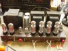
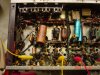
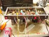
OK, Here are some 'beginning' pics of my unit. Note the one replaced coupling cap w/ the light blue robin's egg version that looks like it got pulled from an old Dynaco. You'll also see the old bias rectifier with the rusted screw on it. There's another intermediate cap that also appear to have been replaced.....another light blue glob. And, the other channel has 2 of the brown turd coupling caps that appear quite different from each other in color. Not sure if either has been replaced....both look 'original'......just different. I'm still pondering the 'test-point' installation issue, and thinking about doing away with the 'X' connection and the 'Common' connection that's taken off 'ground' with the .47 ohm resistor. In today's world, I don't really see a purpose for either.....and that's 4 test-point locations that I could use for the output tubes. Then I'd only need to locate 2 more some place.....and that's a LOT easier than drilling 6 holes into the thing. Anyway......here' it is...'tubed up' and in listenable condition. Just 'not stellar' as yet! Soon to be...... I hope! WC
 

Attachments

  • DSC02431 (2).JPG
    DSC02431 (2).JPG
    143.7 KB · Views: 66
  • DSC02427.JPG
    DSC02427.JPG
    147.3 KB · Views: 64
  • DSC02428.JPG
    DSC02428.JPG
    152.4 KB · Views: 58
  • DSC02430.JPG
    DSC02430.JPG
    152 KB · Views: 61
  • DSC02426.JPG
    DSC02426.JPG
    154 KB · Views: 59
Since I had gotten used to the SA100 and it's external test points (including the two I added), I thought it would be an excellent enhancement for the SA300. But once I looked at the circuit and the amp's real estate, I realized it wouldn't work the same way as with the SA100 and wasn't feasible with the SA300.
When I talked about drilling holes for access, I was talking about through the removable side panel to the bias and hum controls. If I were to split the bias circuit into left/right and wanted access without removing the side panel, I would drill 2 holes and cover them with metal plugs. Those same metal plugs that cover the AC/DC balance controls are available in chrome finish at Lowes, they would only need to be painted to match the amp. Done in this manner, I think the amp wouldn't look so bad and I don't think anyone would even take notice, much less complain. However, given that the side panel is easily removed (by design I suspect), drilling is not even necessary to access a single or dual bias controls. Splitting the single bias control into two would remove the need for a closely matched quad of output tubes, which makes perfect sense to me, but isn't even an absolute necessity. And honestly, how often do we check bias? That's when I came to realize that fabricating individual bias test sockets (similar to those sold on ebay for $20) for each output tube would actually be the simplest and most accurate way to go with the least overall effort. I have one VTVM, two VOM's and six DMMs (including 4 Flukes) so anytime I want, I could get a complete picture of the amp at a single glance. Using this DIY approach, I can custom construct test sockets to read any parameter with a minimum amount of effort. I can build them to read voltage and currents for the plates, screens and cathodes simultaneously. After much thought, it's the only scenario for which I cannot find a negative aspect. It's the ultimate tube tester because it tests each tube in use at real working voltages. I'm the first to plead guilty when it comes to over-engineering, but when you get down to it, individual bias test sockets for each tube makes the most sense to me because they can can be used on any amp.
I liked Dave's solution employing the (rarely used) terminals on the SA100 speaker strips, but I thought replacing the 3 terminal stock test points with a 5 terminal strip was even better in that it was more intuitive and obvious. I was, as he suggested in another post, doing what Fisher probably should have done in the first place. If you look at some of my pictures and compare them to a stock SA100, a five terminal strip fits and looks like it was part of the original design. The biggest problem was finding a five terminal strip, which I did, including a few spares. Installation was a snap, no major surgery. My governing principle is to make any project look as though I was never even in there and why I wanted to see an image of a factory condition SA300B amp.
With my SA100 now running stable, I hardly ever find the need to check bias, only when I swap tubes or when my ears seem to play tricks on me. I like to switch tubes around every once and a while because they sound different, so the bias gets checked often enough anyway. I have sets by Amperex, Sylvania Black plates and GE-7189-A, and they all sound different. Depending on my mood or the kind of music I'm into, I'll swap tubes to get the best sound for my mood.
The first amp I rebuilt was the Dynaco ST70 using the VTA driver board. The VTA board has 4 adjustable pots and provisions for external test points for the four individual EL34's via the front preamp octal sockets. An empty octal plug, test wire, banana plugs and two DMM's-I had a simple and very safe way to plug in, observe and adjust the bias and balance of each channel without ever having place a test probe near a high voltage source, inadvertently slipping the probe and causing damage. (Read "Screwed the Pooch" on this forum for an example).
Audion:
What Dave noted about the SA100 riveted ground terminals does not apply to the SA300. As I recall, the chassis of the SA100's have a high copper content, and riveting the dissimilar metal of a grounding lug creates a recipe for a galvanic reaction between two dissimilar metals resulting in corrosion and resistance between the two dissimilar metals. The Chassis of the SA300 isn't the same, and I haven't noted any corrosion.

You changed the couplers (Jensens and Orange Drops) but what about the electrolytics used for bypass? Are any of them near a source of heat? Like the orange drop next to the fat resistor by the AC/DC controls?

Any chance you simply had a tube go bad? It happened on my Dynaco ST70 recently after sitting idle for a few months. Red plate out-a-nowhere, and the tube was gone. Fortunately, that amp doesn't require closely matched quads as each socket is adjustable. Swapped in another tube, adjusted bias and good as new. Maybe it was just that tubes time. Part of God's plan.

5. On the SA-300, there is a ground terminal and next to that a common terminal. On mine, I used the common terminal. The only thing separating the common and ground is a 0.47 ohm 5 watt resistor on each channel. That's an oddity. It's possible that the SA-300-B may have speaker common terminals that are not at ground potential to support the use of a summed center channel output. Dave has mentioned on the Fisher 400, X-1000, and X-101-C restoration threads that the speaker common not being at ground potential is an issue when testing.
03-28-2014 02:57 PM

It's my understanding that you're supposed to clamp the negatve probe to the chassis for ground when testing voltages (at least that's what I do).

I could be wrong here, but on the SA100 I thought the "x" terminal served as the ground terminal for speakers needing more damping factor and one speaker connected from Channel A common to Channel B common was an amplified mono amp (when the "stereo/mono" switch was switched to mono). I never personally verified this so I am only speculating.

And why the inrush limiters? I didn't think they were necessary with a GZ34 rectifier because it brings the B+ up slowly? Did you do it to reduce input voltage? Do they get hot affecting the nearby hum adjust pots or the rectifier tubes?

To all:
Regarding the Selenium Rectifier Stack...get it the hell out of there! When they blow they release a toxic gas. I didn't even want it around if it got heated by the nearby diode.

Selenium dioxide is formed when selenium is heated in air. Direct exposure to selenium dioxide is, therefore, primarily an occupational hazard and not likely to be a risk at hazardous waste sites. Selenium dioxide forms selenious acid on contact with water, including perspiration, and can cause severe irritation. Acute inhalation of large quantities of selenium dioxide powder can produce pulmonary edema as a result of the local irritant effect on alveoli (Glover 1970). Bronchial spasms, symptoms of asphyxiation, and
persistent bronchitis have been noted in workers briefly exposed to high concentrations of selenium dioxide (Wilson 1962). Kinnigkeit (1962) reported that selenium dioxide concentrations of 0.007–0.05mg selenium/m3
in a selenium rectifier plant producedslight tracheobronchitis in 9 of 62 exposed workers

Selenium rectifiers

Selenium dioxide is the major compound produced when a selenium rectifier is overheated. It can cause severe burns to the mucous membranes and severe respiratory tract, skin, and eye irritation. It can also promote allergic reactions with the skin. Fortunately it is not considered a carcinogen.

Another fortunate thing is the awful smell which gives it away. If you smell something really rotten, like decaying onions and garlic, coming from your equipment, it is best to leave the area immediately, opening some windows on the way out. Allow the selenium dioxide vapours to dissipate for several days before you go back - you will not want to go back very soon anyway!

 
Rich,

Some interesting comments you make! I didn't realize there was a hazard involved with old selenium rectifier failures.......at least beyond the results of the loss of negative bias. I've seen inoperative units...but never actually witnessed a failure. So, never seen the smoke, smelled the fumes......or heard the pop! But, I do tend to replace them, and typically use the 1N4007 diode in their place, though I understand that there are some better choices. I just don't have them 'in stock' here at my home, and I do have a lot of 1N4007s.

I'm still a bit confused by this 'access' panel of which you refer to. My bias control and two hum pots appear to be located the same place yours are....but short of removing either the bottom of the amp, or the end cap....... I don't see how you'd get to them to 'tweak' them if necessary. I like how you did the 4 test points on the SA100.....and you're right...they DO look as if they were original. But, as you mentioned, the SA300 doesn't lend itself to the same type of 'conversion. However, I still think there's no truly useful reason to keep the 'Common' or 'X' terminal hookups within the amp. And, as there are 2 of those for each channel, I see those as being two reasonable places to hook the contacts to the 4 output tubes. As Don says: The chassis can be hooked to for 'ground' connections. But, in checking bias at the tubes....the 'draw' would have to be measured between the tube socket junctions of both pins 1 AND 8 together.....as measured across a 10 ohm resistor connected from that point to the top of the Cathode resistor/Bypass Capacitor junction......NOT directly to ground. So, a third connection has to be made ON THIS AMP.....for purposes of measuring actual tube current draw. DC Balance can also then be measured by achieving ZERO volts between the two bias test points for each tube.

In trying to find a reasonable place for that third connection..... I've also been trying to figure out just what reasonable use I might have for that second RCA plug on each channel. I'm thinking that may be the best 'sacrificial' location.......and it could be easily re-purposed for this. The question is: What do I really lose if I do away with it? Honestly, I'm not sure I really know why it's there in the first place? Do either of you? I know it's considered a 'filtered' connection....but I've seen it labeled as both an 'input' and an 'output'......depending on where you look. Perhaps it was intended to be used as a 'loop' connection of some kind? But, in considering a typical power amplifier, it really only has 2 inputs....just right and left. So, no real point in this second set of connections that I can figure. Please correct me if I'm wrong.

Looking forward to getting back into the amp on Monday. I've got a few things to do during the day......and the entire week to play with it. But, beginning on 4/7, I'll be 3 weeks of contract work taking me away from the shop activity. So, what ever doesn't get done this week, will have to wait a while!!

Rich....again.....good info. Don..... keep those cards and letters coming.....

Tom
 
Last edited:
My bias control and two hum pots appear to be located the same place yours are....but short of removing either the bottom of the amp, or the end cap....... I don't see how you'd get to them to 'tweak' them if necessary.

The end cap is what I'm referring to, it can be easily left open exposing the bias pot(s) while the amp is up and running on its feet. When I'm biasing an amp, I like to do it before and check it after it's been played for a while. Leaving that end cap off allows me access to the bias pot. I can only think it was made removable for that purpose because the SA100 does not have a removable end cap. Another reason I think the bias test sockets are a good idea-the amp can be measured without having to invert it and remove the cover. Absolutely zero chance of a probe or clip slipping and causing a short.

In trying to find a reasonable place for that third connection..... I've also been trying to figure out just what reasonable use I might have for that second RCA plug on each channel. I'm thinking that may be the best 'sacrificial' location.......and it could be easily re-purposed for this. The question is: What do I really lose if I do away with it? Honestly, I'm not sure I really know why it's there in the first place? Do either of you? I know it's considered a 'filtered' connection....but I've seen it labeled as both an 'input' and an 'output'......depending on where you look. Perhaps it was intended to be used as a 'loop' connection of some kind? But, in considering a typical power amplifier, it really only has 2 inputs....just right and left. So, no real point in this second set of connections that I can figure. Please correct me if I'm wrong.

I would absolutely recommend against using any RCA jack, especially the one closest to the input jack. Why? However remote, there is a chance a preamp's line out could accidentally end up in the wrong RCA jack. Accidents happen. It would be a fundamental error to use an RCA jack as a test point. Same reason why Oxygen and Acetylene tanks have different threads, it makes it impossible to hook up a tank to the wrong line.
Even if you were to change the RCA input jack to something else...do you think it's a good idea to have any kind of voltage near the amplifier's sensitive input jack?

I just think the octal bias test sockets do what they're supposed to with zero liability.

The only enhancement to the amp I see is splitting the bias supplies into two, and I'm not even sure if that's necessary. I want to run the amp a while and see if it's something I find necessary.
 
Last edited:
I've been toying with changing the way pin 1 and pin 8 tie together.
I looked at my Fisher X-1000.
The Fisher X-1000 has a bias pot for each channel and a DC balance pot for each channel (pair of EL-34s).
In the X-1000,
1. pin 8 from each pair of EL-34s ties together.
2. pin 1 from each pair of EL-34s ties together.
3. There's a 10 ohm resistor tied between the wires tying pin 8 together and tying pin 1 together.
On the X-1000, the tie point from pin 1 goes to ground.
On the X-1000's schematic, with a 10 ohm resistor between each pair of output tubes' pin 8 and pin 1, and with pin 1 tied to ground, you adjust the bias control to get the test point voltage at the pin 8 wire is 0.86 volts DC.
We might want to drop the voltage at those points to about .70 volts for closer to 35ma dissipation per tube at idle.

In the SA-300, Pin 1 and Pin 8 are tied together at the tube and each pair of tubes is tied together. In each pair, a wire runs to the 50 ohm 5W resistor in parallel with the 150 microfarad cap and both go to ground.

On the SA-300, the tie point from pin 1 would go to the 50 ohm 5W resistor in parallel with the 150 microfarad cap that ties to ground. In this case, pin 8 would be on the other side of the 10 ohm resistor and there'd be a 10 ohm resistor between each pair of pin 8s and pin 1s.


I expect that, in this application, the test voltage at that test point should be approximately .86 volts above the value on the other side of the 10 ohm resistor or whatever voltage makes sense for how you want the tubes to idle.

A couple of questions.
I'd like to put 100 ohm screen stability resistors in.
1. In this configuration, the screen is on pin 4, correct?

2. I'm having trouble figuring out exactly how the bias pot (R7 on the SAMS schematic) connects to the output tubes. If I understand correctly and it connects at the DC balance point, then it's adjusting the negative grid input value. Is that correct?

3.If that's the case, is your desire to split the bias into two pots to make the negative grid input value controllable per channel?

Thanks,
Don
 
Last edited:
Heyraz, I agree....shouldn't use the RCA plug as a test point....though some builders do just that. I wouldn't......and in the case of this amp, were I to use the location of that second input....... I WOULD change the jack. As to voltage location...... we're talking the cathode bias line here.....not any HV, or even 'AC' enough to cause a problem, particularly if the input line were then separated and a nice small piece of shielded cable used.

Don, I think you're correct about the location for the 100 ohm grid protection resistors. BUT......my understand on those is that they're a lot more significant if the voltage disparity between that grid and the plate is closer. The schematic shows there to be 5 volts difference. I'm thinking a measurement may be worthwhile. I also understand that a 'target' of about 10 volts is good.....but again, I'm NOT the expert in this area. Just regurgitating some of what I've been told in the past.

Regarding your comment #2, I'm a bit unsure just how the effect of separating the pin 1 grid from the cathode would work in this amp. Remember, this amp is BOTH 'adjustable' and 'cathode' biased. If I'm not mistaken, the X-1000 is ONLY 'adjustable' biased. And, so we're on the same page with the definition of 'adjustable' bias.......I believe this is also often referred to as 'fixed' bias. But, only 'fixed' when no adjustment pot is involved. In either case, 'Cathode Bias' is still what I'd call 'the other method'! I consider this amp rare in that it's my first experience where it contains the elements of both 'adjustable' and 'cathode' bias. For the record, DSG advised against the separation of Pin 1 and Pin 8. No detail supplied.....so maybe still a good possibility for further evaluation?

I think the answer to #3 is 'YES'.....just like the X-1000 or the Fisher SA-100, or even the Scott 299C or D or 233. I believe all those amps have both bias adjust pots for each channel.....which elevates or diminishes the negative voltage going to each pair of output tubes.....and Bias Balance pots....which simply allow the negative bias voltage going to each output tube to be adjusted to either tube so both tubes bias equally. Once both tubes are 'equal'....the the bias adj pot can raise or lower the overall bias to the pair. Do the same thing for both sides and you end up with a perfectly balanced output in spite of the disparity between individual tubes.

Personally, I LOVE this set-up......as I've always been able to dial in most any amp that has it to an appropriate bias level on each output tube, plus it allows me to use 'not-so-well-matched' pairs in the quad. The 'mod' going around for the Fisher 400/500...commonly known as the IBAM mod, is really just this circuit as applied to the 'fixed' bias design of those amps. I've yet to actually build the IBAM.....but I've studied it, purchased the parts for it, and planned to do one on one of the ROWE Juke box amps I've been playing around with. Which, BTW.....I am gaining more and more respect for as time goes by. Like I said...... I did an A/B between this Fisher SA300 and one of these old Rowe amps, and the Rowe amp outperformed the Fisher quite noticeably in virtually all categories. So, hats off to Rowe for their product.....cuz even if I get the Fisher amp to ultimately outperform the Rowe......the old Juke Box amp will still have proven itself to be an outstanding product.

OK.........onward.

TSD
 
Last edited:
A few comments if I may:

1. The Com and X terminals on the X-202, SA-100, and SA-300 (any version) are for the pure purpose of reducing the damping factor of the individual amplifier channels if need be. While the normal (high damping factor) speaker connections are to be made between the chosen impedance and Ground terminals, lower damping operation requires the speaker low side connection to be made to the Com terminal, which is also strapped to the X terminal in this scenario as well. The strap between the Com and X terminals is only to be in place when the low damping option is used. Additional external resistors can also be used to adjust the lowered damping factor if so desired with these terminals as well. These terminals on any of these models have nothing to do with any type of center channel output -- powered, or otherwise.

2. The elevated Com terminals (above ground that is) are present on (at least) the X-101C, X-202B, and X-1000, but not on the Fisher 400 receiver. In the "affected" units, the Com terminal is elevated above ground to accommodate a powered center channel speaker feature, which no version of the SA-300 includes.

3. Selenium rectifiers in positions providing significant current (as in heater supplies, etc) are classically known to fail over time, and should be replaced even if currently good. However, selenium rectifiers in very low current applications (such as bias supplies) are virtually never known to fail. The key is the heat produced in operation. Those units required to pass significant current also generate significant heat because of the voltage drop produced across them. That is why when selenium rectifiers are replace with silicon rectifiers in high current applications, an additional dropping resistance is required to bring the voltage back in line. However, in low current applications, there is virtually no voltage drop, so there is no heat, so there is virtually no failure. Replacing a selenium rectifier in a bias supply with a silicon one, and adding the oh so often recommended added dropping resistance can often result in not being able to bias the output stage because the available bias has now been reduced. This was exactly the scenario with Don's X-1000 when I first received it: The selenium bias rectifier had been replaced as "standard practice", along with adding an additional dropping resistance as "standard practice", with the result that the unit could not be biased properly. This is no hit on Don, as it had already been done before he received it. But that was the case none the less.

This type of unfortunate information starts the same way that the old cathode stripping issue did with SS rectifiers. Everybody says to delay the B+ from SS rectifiers to avoid cathode stripping in output tubes. Cathode stripping is an engineering problem to consider -- in transmitting applications where thousands of plate volts must be delayed until the filaments have reached operating temp. Otherwise -- in those, AND ONLY those applications -- cathode stripping can become an issue, but not with tubes classified as "receiving" tubes, and the voltages they operate at. The common RCA RC-30 Tube Manual is called the RCA "Receiving Tube" manual for a reason -- to distinguish the class of tubes it covers, versus the commercial and industrial tubes covered in other manuals.

And so it is with selenium rectifiers as well. Somewhere along the line, just as with cathode stripping, somebody heard that selenium is bad -- and it is bad stuff (but there's a bunch of bad stuff in electron tubes as well). But that doesn't mean that selenium rectifiers should be "categorically" replaced without first assessing the circuit they operate in. The selenium rectifiers used in Dynaco PAS preamplifiers for the heater supply virtually ALWAYS go bad. The selenium rectifiers used in the bias supplies of the Dynaco MK II, III, and IV power amplifiers virtually NEVER go bad. The point is, in electronics, there is rarely a one size fits all recommendation, when it comes to the NEED of replacing various components.

No doubt that some will simply feel more comfortable removing all selenium devices from their equipment, and that's fine. But having a better understanding of when they really NEED to be replaced can help to make sure they are getting all the return they think they are getting when such replacements are made.

4. Fisher commonly used different voltage rated coupling caps from the phase inverter plate and cathode elements to the output tube grids in a number of their models. This is particularly true in their SS rectifier models, where the plate voltage of the phase inverter tube can become quite elevated until the inverter tube warms up. With the coupling cap at that location also typically having a negative voltage also impressed on the other side of it from a fixed bias supply, the voltage rating of the cap must be increased to handle the combined turn on surge. However, with the cathode coupling cap, no such problems exist, as there is no cathode voltage until the phase inverter tube conducts (or much reduced voltage anyway), and at that, the cathode voltage -- when present -- is always much lower than the plate voltage . Therefore, a cap with a much lower voltage rating can be used at that location. With profit and component size always a consideration, the nod for a lower voltage component made sense at the cathode coupling cap position. It's extremely doubtful that using different voltage rated caps -- but of the same capacitance value -- was done for any purpose of voicing their units.

Just thought I'd add a little levity to the conversation!

Dave
 
Last edited:
Dave, the 'Gravity' of your remarks......is never 'levity' in and of itself. But, ALWAYS appreciated.

I'm now up-dating the results of the swap to some 'good' rectifiers. I did a current (no pun intended) voltage test based on available wall supply at this moment. In so doing, I saw 381 VDC AFTER the second 15 ohm resistor with the JJ rectifiers. For purposes of specificity, this would be between R66 and R67.....where schematic shows voltage to be 410V. I installed two known good "Made in England" Mullard rectifiers.....thinking that I'd see an increase in voltage. To my surprize, voltage was EXACTLY the same!! BOTH sets of rectifiers were outputting identically, and my voltage reading of 381 was the same for both pairs. So, the JJs are now back in the amp......and frankly, I'm not sure what to do next to this thing!

My hope was that I'd see some 30 volt jump.....or even more considering today's higher wall voltage and the 'usual' problem of B+ being too high. But, the situation remained precisely where is was regardless of rectifier type used....which may be a pat-on-the-back for JJ. I've not thought much of their rectifiers in the past, but figured using 2 of them in this one amp the pair would likely hold up. Seems they're doing OK.......by virtue of this very basic comparison. Certainly not a full blown working comparison....but, this has got to be some indication that they're working reasonably close to intended parameters.

It may be time for me to step away from this amp and decide what it's real future is. I have an old HK Citation V that has been sitting for nearly 5 years now.....complete with a bag of parts obtained from Jim McShane to essentially rebuild the amp. So, maybe I should go tackle that project since there doesn't seem to be too much more to do with this amp aside from tossing parts into it...which doesn't really seem necessary. Or, maybe I should do a 're-cap' and then re-evaluate it. Replace the coupling and intermediate signal caps....then 're-try' the thing and see if performance improves. I hate to tamper with the amp's 'authenticity', but then I guess the existence of those light-blue gummy-caps is reason enough to justify replacing the signal caps throughout. I believe I have sufficient 'poly-caps' on hand to do that with. While not 'high-dollar' PIO pieces, I've been quite pleased with the results of doing this in the past.....so, short of any other 'suggestions'...that may be the next order of business. WC
 
Last edited:
We might be making this more difficult than it should be.
I can't see this as a cathode biased amp as I understand cathode bias, where the cathodes of the outputs are tied together and used to power other tubes's heaters.
The cathodes of these go to a 50 ohm 150uf RC network and then to ground.

What I see is a bias pot that's wired in series with the DC balance control of the two channels. This is the negative grid bias value of approximately -25VDC. I think you can adjust each channel's negative grid bias using the DC balance for fine tuning after setting the bias control.
 
Last edited:
Don,

This amp is 'both' fixed biased and cathode biased. In a good many amps the cathode resistor that, in this case is the 50 ohm resistor....that is 'replaced' by the filament string on some pre-amp or signal tubes. BUT....that's PURLY re-purposing some available voltage......NOT what defines the category of bias type.

In a good many amps, there is a design factor that permits the use of the voltage being generated in the 'negative' winding of the PT to not only be used for negative bias, but also to power some filaments in the pre-amp section. In other amps, the cathode current can do this as well. But, fundamentally (as I understand it) the basic difference is in the introduction of a 'negative' voltage to the input grid on the output tube. If this is done, then the cathode can be tied directly to ground and current will flow properly since the grid side sees the negative over ground. If no negative voltage is applied, the a resistor is applied at the cathode...which essentially creates the same voltage relationship for current flow. But, what's unusual in this 300 is that there is BOTH a cathode resistor (which could have been filaments from signal tubes if it had worked out that the tubes could supply the same needed 130 ohms).....AND...the amp also has a negative voltage supply on the input grids. So, 'combination' cathode and fixed bias. Again. remember that 'fixed' and 'adjustable' are synonymous other than a 'pot' to make the 'fixed' negative voltage 'adjustable'.

The 'cathode' bias amps are often referred to as 'self-bias' amps..... which gets into another whole discussion. I'm not so sure I'd use that phraseology to describe cathode bias. But, there is some justification for it as the cathode resistor does act to work with the current being pulled during periods of high demand to keep the amp stable. But,..... this is where you get into the whole discussion of the real detriments of 'cathode' bias.....and where Dave's EFB comes into play. In fact, the ST-35 is a good example of 'cathode bias'.......(non-EFB version).....as you'll see the amp has no 'negative' voltage supply......and all 4 cathodes feed into one cathode resistor (95 ohm / 5 watt)....and you'll also see there is a bypass cap in there as well for all 4 tubes. If someone were to introduce a negative bias supply on top of this, then it too would be a 'combination fixed/cathode bias' amp. But, never seen one like that......

Anyway...... hope this helps some. I suggest you take a look at a Dynaco ST-35 schematic....and you'll see the cathode bias scheme. Then look at your SA-100 schematic and you'll see how the cathodes all go directly to ground. SA100 has a negative voltage supply.....ST-35 does not. SA100....'fixed' (or 'adjustable') bias amp, ST-35....'cathode bias' amp.

TSD
 
Last edited:
Yeah, I guess you have to be in a place where it can finally make sense.
I went back to the tronola website and reread Dave's articles about maximizing power tube life and took a quick look at the A New Look at an Old Friend article.

Now I get how to see Cathode bias.

I am going to put 100 ohm resistors on those screens though. The plate and screen in this design are very close in voltage. Even though this is a tube rectified circuit, the AC voltage here can run quite high, causing arcing conditions. Four resistors is cheap insurance.
 
Last edited:
Back
Top Bottom