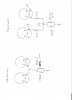
OK......sorry if this drawing doesn't make it.....or if it doesn't make sense. It may also require you to download it and spin it 90 degrees. But, hopefully you'll get it and be able to make sense of it. NOTE: Pins 1 and 8 stay tied together. The resistors go between both pins and and the 'top' of the R/C network which is the 50 ohm resistor and the 150 uf cap. In the original design, both tubes from each channel go to the one network....so that doesn't change. And, the network is 'grounded' on one end...and that stays the same. The ONLY change is that the connection between each tube and it's corresponding network...currently just a wire, now that is replaced by the 10 ohm resistor. And, instead of reading 'bias' between ground and the pin 8 of each tube, you'll read it between pin 8 (still connected to pin 1) and the 'top' or ungrounded side of the R/C network. According to DG, that reading should be about 70ma. However, you can also connect between each pin 8 of the given pair....and use the DC balance control to get a 'zero' reading on a DVM. This will simplify the DC balance procedure. You can't do that now and they are essentially 'hard-wired' together in going to the R/C network. But, with the 10 ohm resistors in place, that will permit this measurement to be done like in the SA-100. Hope this helps....... TSD