• The move to the new server is done. There are some software and database maintenance updates in process. This has us passing the hat around to help out. We appreciate any donations. Seriously, even a dollar helps. The payment page may be found here - https://www.audiokarma.org/support.html

Fisher SA-300B Set-up and Bias Adj. Question

Well, you guys have both pulled ahead of me! I'll take credit for getting my 'playing'....but as to the proper analytics.... I have to surrender. Don, I'm glad yours is playing! Raz, sounds like yours is making you pretty happy.

I think I got a bit disillusioned with mine after hearing it play a couple of times and just not being all that impressed. But, I truly think my unit has problems in other areas; like coupling and signal caps, proper bias level, and I'm still not all that convinced that it's operating at the correct voltage. IIRC, the last known voltage check on my unit had it at around 380 volt at the B+....which was 30 volts light. And, if I also recall correctly, my filament voltage on both the tubes and the rectifiers was right on the money. So, I think 'filter caps' are in order on my unit as well. I started to order these, got interrupted....and haven't been back to the parts store online catalog since. Maybe later tonight.

Anyway.....KUDOS to both of you! Wish I could hear them both! Would be great to play round-robin with these....swap 'em off for a week and just hear what we've all managed to create! While the internet does bring us all together in some ways, it's still not substitute for being in the same basic city.....or even state (let alone neighborhood).

Keep up the fine work! BTW, had burgers on the Barbeque tonight! A sign of spring! At last..........


TSD
 
My point was to get mine running and then, over time, learn some baseline testing using it.
I think it can do better than its performance in stock mode, but that stock performance needs to be baselined.

I suspect the testing will reveal that some tweaks will be necessary to make it perform as it should. That's tweaking spot is where I'll run into trouble.
 
Raz,

Just curious, did you 'check' your 1 ohm resistor for variance? I know you don't want to be re-building these gems......and they look very nice BTW......but I was wondering if the variance on a 1 ohm resistor was such that the 'accuracy' of the number might be better across a 10 ohm resistor? I think I read that some place......and it's stuck in my head......and I'm just not really sure. So, you can tell me........if off by ie 2% on a 1 ohm resistor.........is the 'reading' on your DVM going to be more or less accurate than if off by the same 2% on a 10 ohm resistor? One other thing.....did you 'swap' your probes to see if the readings stayed the same, or if there was any kind of change that might indicate some kind of variance in the resistors? Those are some first-class meters I might add!! Very nice work!! Tom D.

First, I agree with the use of 1% resistors. That precision isn't needed for the circuit, but it certainly makes for a more accurate measurement of a very critical parameter.

While meters may be less accurate with the lower resistance due to the test lead resistance and contact resistance being a larger part of the total, as long as it's consistent, the end result should be as good. Mainly because if the absolute value isn't perfect, not a huge problem, but the match between values does need to be accurate.

So, is that a meter, or is it a fluke?
 
IMG_4153_zpse04ac4b0.jpg


So it would appear that this amp could benefit by the installation of separate bias supplies to each channel. The bias was initially set according to the instructions in the service manual. One side was consistently higher, regardless of what set of test sockets I was using. I was able to set the dc balance very easily though.

That's all for tonight, folks. I'm going to pour a scotch and check out the amp. I just installed new tubes all around.

Three Flukes outa four aint bad (and that old Micronta was just as accurate).
 
Mine runs into the same problem in biasing the pairs. One pair is hotter than the other. My readings are surprisingly similar to yours heyraz.

VAC In 120.5. Surprisingly low tonight.
410 source reads 400 after a thorough warm up.
395 source#1 reads 385
395 source#2 reads 387
350 source reads 339
290 source#1 reads 295
290 source#2 reads 297
Bias input voltages at pin 5 of EL-34s reads between -21v+- 1 volt depending on the tube. This is with the pair in V3/V4 set up to dissipate approximately 65 ma and the pair in V8/V7 set up to dissipate approximately 75ma. I can't get V8/V7 down without having V3/V4 drop below 60ma.
The 12AX7s and 12AU7s are all well balanced between triodes and all are powered with pins 4&5 jumpered and pin 9 connected with about 6.42 volts AC on the filaments. That's just a bit hotter than I'd wish for in a perfect world.

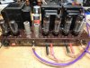
The specs on this thing look pretty good. It was sounding better after it was good and warmed up. I took some pictures. The night shot is hand-held and I didn't hold it steady enough, but you get the idea.

Photos
attachment.php


attachment.php


This one was a time exposure about five seconds long. I may cool down the bias on the tubes a bit more, but they're not red plating like this photo would make you think. None are over 70ma dissipation. I'll drop them 10ma though because the amp did get fairly warm.

attachment.php
 

Attachments

  • Fisher SA-300backtostock1.jpg
    Fisher SA-300backtostock1.jpg
    105.6 KB · Views: 66
  • backtostock2.jpg
    backtostock2.jpg
    94.6 KB · Views: 66
  • backtostockinthedark.jpg
    backtostockinthedark.jpg
    43.4 KB · Views: 65
Last edited:
Don,
First of all, I want to thank you for turning the fuse cap right side up. It was starting to mess with my head.
Wow, after a few hours of work on my amp tonight, I was mentally shot and needed a power nap. Most folks don't understand the term "getting into the zone" and how much it takes out of you, but that's what happens to me when I get going, I don't feel hunger, thirst or fatigue. I don't care about the first two, but when I realize my concentration is fading, I simply walk away before I can make a mistake. Safety First Always.

I haven't gone over the power supply yet with a fine tooth comb, probably because preliminary tests of the amp were in range and it didn't sound too bad with the tubes it came with. When I do address it I'll probably rip it out and redo it right because the last guy to work on it did such a messy job with the poorest looking solder joints that I'm doubtful of it's longevity. He didn't even solder down the FP twists, so who knows how well that ground connection will last? He also stretched a wire to solder it to one of caps and there's barely a solid physical contact. Before I do that, I want to learn more about splitting the bias supplies and see if I can get it to fit in. I'm not even sure yet what kind of pots to use (carbon or wirewound), so I need time to research and learn. I want to do the bias supply at the same time as the power supply. The amp works well, I can hold off for a while.

Anyway, I wanted to let you know that I replaced all of the tubes tonight from my collection, and wow. Since I fell in love with my friend's SA300B, I've been subconsciously purchasing tubes over the past few years hoping I'd run across another SA300B in the future. I've had the opportunity to swap tubes on his unit so I knew what I was looking for.

First off-the Rectifiers. Mullard Fat Base F31 or F32 with flat plates or 4 notch plates. They are the heart and soul of this amp. The 7 notch or copper Mullards pale in comparison, don't bother. The new Sovtek's or any other label from that factory are utterly pitiful by comparison. My amp came with RCA's, which weren't bad, but not in the same league as the Mullards.

Same with the output tubes-Mullard double halo-what a sweet sounding tube. My amp arrived with Electro Harmonics (Russian) and it was harsh.
I replaced them with some nice Mullards from my collection and listened to Brazil 66 tonight. I want to leave my wife and marry that chick-her voice sounded so warm and seductive tonight.

12AU7's and 12AX7's-Mullard or Amperex, with the edge going to Amperex for my taste. That plant in Holland used to out some quality tubes. I'm not too crazy for Tele's-they're a little too bold for me. Sylvania Gold Plate 12AU7's are real nice too- I used one in my son's Dynaco ST70 with the VTA board. That Sylvania was the best of the bunch for that amplifier position.

I hope you figure out your voltage situation soon. Good luck.

Rich
 
Rich -- Any full size (i.e. .5 watt) carbon pot with a linear taper is more than adequate for use in the bias circuit.

As a suggestion, replace the existing 5K bias control with two 10K controls with their tracks wired in parallel. You'll need to add in another C6 (Sams) for the wiper of the second control, with each wiper then serving the DC balance circuit of one channel. That should do it.

Good luck with your 300!

Dave
 
I'd always found the bias circuit to be a bit twitchy in this unit.

Oh, and like heyraz, I found one of the can caps wasn't soldered to the chassis at the twist-locs. so, I put some flux on and soldered it. There's always been just a touch of hum. I'm hoping this move will help . . . but, one thing at a time. On to the bias system change out to a channel-based bias circuit for negative voltage to pin 5 of the pair of EL-34s.

I know that the selenium rectifier had been changed out, but the amount of modification in the bias circuit that someone had done was unclear. After the selenium rectifier, a 15k resistor is in series on the schematic. The value in my circuit was a 680 ohm resistor. No wonder the measurements were off and I was having trouble getting the bias down low enough. My old Shugangs had been run quite hard. Rather than trash the tubes, I have to say that they performed fabulously considering that they were running well over 80ma dissipation per tube.

The 10uf 150v caps were replaced with 15uf 150v caps. That should be Ok, but the caps, shown in blue below, are larger than I think that section can afford.

A 15 k resistor is going off the pot to ground, where in the schematic, that value should be 390 ohms.

There was a .1uf 600 volt cap, used by the AC Bias switch, crowding that space. That should be a 400 volt cap. I'm going to replace it with a 400 volt cap and move the cap to free up some space.

The bias pot's output goes to both DC bias controls. Two pots, terminated to ground with 390 ohm resistors, and in parallel with 10uf caps with the + to ground will now each individually go to the DC bias controls. I only have 10uf 100 volt caps, and they should work fine, but I will have occasion to happen by the local electronics store tomorrow night, so I'll see what they have.

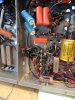
I'll have to get some short standoffs for a new little circuit board. I've taken a picture of the stripped out bias area, with the bias pot, the .1uf resistor, and the bias wire removed.
attachment.php
 

Attachments

  • SA300biasundone.jpg
    SA300biasundone.jpg
    104.7 KB · Views: 54
Last edited:
I can honestly say that you guys are REALLY making it hard for me NOT to just go tearing back into my amp. But, with starting this new job tomorrow, I need to focus, and I know the 'mental' demands over the next 3 weeks will be enough for me. If I cloud that focus by thinking about my 300........ I fear I may fail to perform on the job properly. So, 'self-discipline'!!!

Anyway......nice job to both of you......and raz I'm really anxious to see how you 'physically' handle the installation of the needed parts. PLEASE post some good pics of that! Don't move too quickly.....remember.......I've got 3 more weeks until I can start following in you and Don's foot steps!!

Thanks Guys..... and Dave, thanks for your ongoing support in this thread as well.

OH....Rax, I'm COMPLETELY in agreement with you about Rectifiers being the heart and soul of an amp. Recall my prior posts in this thread about 'voltage' ranges. However, I believe I also mentioned that just having proper voltage under no load was NOT an indication of how the power supply would perform when the amp was operating. That's where that rectifier performance can REALLY make a notable difference. Likewise those output tubes! Some amps can work well with most any tubes...while others are VERY sensitive to tube-type! This amp appears to be one of those where 'vintage' can mean everything!!

Tom D.
 
Tom,
We're leaving a bread crumb trail for you and any future readers.
The job comes first and this can be for your vicarious night reading pleasure.
 
LOL.... Perfect! Thanks Don....... at least I can maintain some level of 'attachment'. TSD
 
Don -- STOP! Please check the actual Fisher schematic for any version of the 300. I believe you will find that in fact it is supposed to be a 390 ohm resistor coming off the rectifier, and a 15K from the bias pot to ground -- the latter as correctly installed in your unit from the get-go. Sams is no friend to you here, as they have the value of these two resistors reversed. If I'm not mistaken, I believe I mentioned that earlier in one of these threads on the 300.

At the heart of your problem is the very thing I mentioned earlier when silicon rectifiers are used to replace former selenium units in bias supplies. Prevailing wisdom has the selenium rectifier changed out to silicon, with an additional resistance placed in series with the new silicon unit to make up for the lower voltage drop of silicon devices under load. Except that, there basically is no load in a bias supply to speak of, so the voltage drop between selenium and silicon devices is virtually the same in such circuits. But prevailing wisdom has the added resistance installed, with the user then wondering why there's not enough bias voltage to bring the output stage current draw down to a proper level. Its because no additional resistance is needed in such cases, with their installation actually causing the problem you are experiencing. In your unit, the "additional resistance" was installed by someone upping the original 390 ohm resistor to 680 ohms. Big mistake.

All you need to do in your unit is to change the 680 ohm resistor coming off of the silicon rectifier back to 390 ohms, and let that resistor supply the two new 10K bias pots. Use a separate 33K resistor off of the bottom of each pot to ground (to help minimize interaction between the two bias control circuits), and install a second 10 uF cap at the wiper of the second bias pot. Each bias pot drives its own DC balance circuit.

Sorry to butt in, but I didn't want to see you place your output tubes in some serious harm's way!

I hope this helps --

Dave
 
My SA300B is on the bench right now and out of service till I complete my mods/repairs. I'll photo document everything I do as I go.
I'm listening to my SA100 right now (loud) and it ain't no slouch. It's much clearer than my SA300B was, but that's EL34 vs EL84. Plenty of power and no edge on the EL84's, my SA300B was a little edgy.
I did listen to an untouched SA300B last night at a friend's house. Much more oomph than the SA100, but still not as clear, nowhere near. My goal is to make the SA300B a little clearer without adding any edge. The SA100 sounds better with more detail at lower volumes (like when my wife is home), but the SA300B is a lot of fun to listen to when she's out. I plan on keeping both amps and choosing on an "as needed" basis.
 
There ya go! Two amps for different scenario's.

1.) The "WILL YOU TURN THAT DAMNED THING DOWN!" amp.
which usually results in you having to use headphones in a soundproof booth, so she's happy!

2.) The "HOT DAMN MOMMA's GONE!" amp. Crank it to Zone 5 AFTERBURNER, and the hell with the neighbor's Windows !
 
This makes you considerably closer than Don to yours truly....... Perhaps a visitation to actually eyeball and eardrum your amp at some point? I think you're about a 2 hour drive. Maybe mid-summer? WC
 
Sounds good to me! I'll have to check my wife's work schedule and make sure she's at work!

The parts I've ordered to repair my SA300B are starting to arrive. First, I'll address the bias situation. After that I want to change the coupling caps.

The coupling caps (0.22uf 600v) are each paralleled with a 1 Meg Ohm 5% 1/2 watt carbon comp resistor. They say carbon comps are the noisiest, and the level of noise is proportional to the voltage. One way to reduce the noise is to increase the power rating of the resistor, so while I'm changing the caps, I'll change the 1/2 watt resistors to 1 watt Allen Bradley RCR 5% carbon comps.

It's no secret that carbon comps don't age well, they absorb humidity and their value increases. And it doesn't seem to matter how old they are, new carbon comp resistors recently purchased from Mouser or Digikey measure just as far out of range as anything NOS by Allen Bradley also recently purchased. Because of this, I've been buying my CC resistors in lots of 20's or more just to find matched sets (they are literally that far apart). I even baked and shellacked a couple of dozen-it didn't seem to matter. Hopefully the shellac prevents any more moisture from being absorbed. I have also noticed that the larger the power rating, the greater the drift, 1/2 watt 47k ohm resistors are closer in value than 2 watt 47k ohm resistors (from the same manufacturer).

Before I realized how much CC's contribute to a vintage amp's "mojo", I used carbon films when I first worked on my SA100, the resulting sound was way too bright. I changed them back to CC's and the mojo returned.

So when you guys get around to working on your amps, let me know if you're looking for a particular value. I'll end up with more resistors than I'll ever need, and if I can help out, I will.

I'll photo-document the bias repair and post the photos when I'm done and satisfied. Wish me luck.
 
What type of carbon film resistors did you use?

I've found carbon films to be a very suitable replacement for most carbon comps, but it may be the formulation in the brand of carbon film resistors that I've used or the careful hand-matching in the two channels that made the difference.

I've been putting in Takman carbon films.

http://www.partsconnexion.com/resistors_takman_rex.html
They're not cheap, but they're good . . . very consistent in value and they don't change in value when soldered in because of the heat.

I think I'm going to take your advice and replace those paralleled 1 meg resistors. I hate the way the old ones look in mine anyway.
 
Last edited:
Back
Top Bottom