• The move to the new server is done. There are some software and database maintenance updates in process. This has us passing the hat around to help out. We appreciate any donations. Seriously, even a dollar helps. The payment page may be found here - https://www.audiokarma.org/support.html

Fisher SA-300B Set-up and Bias Adj. Question

I'm going to 'fess-up' here and admit that my experience hasn't led me to being particularly biased toward either Carb.Comp or Film resistors. However, that said, I have experienced the 'noise' factor of Carbon Comps.......as well as the somewhat 'bright' factor associated with the film resistors. But, as most of what I do involves making something that's 'broke' work again........ what ever resistor I can get my hands on is usually what ends up in the unit.

Raz, if you end up with a 'surplus' of parts for re-doing your amp....and want to just put a 'package' together.....I'd gladly work with you to just buy it.

WC
 
I've used Xicon, Vishay and Koa Spear carbon films on my SA100 and other amps. They're all very clear, but I realized it was too clear because it was actually bright. And that was just at low volumes. When I raised the volume, it became edgy.
As bad of a rap the carbon comps get, they're supposed to be the best as grid stoppers because they don't behave like an antenna. So when I returned the grid stoppers to carbon comps, things got better. I worked backward and things continued to improve.
So for the SA300B-I'm going to stick with carbon comps wherever replacement is needed. Fisher used RC, I'm using RCR, which is a military version and has 5 color bands instead of the usual 4. Hopefully, they're actually built better.
It's a classic amp with a classic sound that uses classic components. I'm trying not to change anything, just make it tighter sounding.
 
About adjust and fine tuning of the sa300-B

I was reading this interesting thread; there are not many discussions about this amp on the net. I do not have the skill to add another bias pot on my 300b so I'm keeping the bias circuit stock for now.
I do have some problems with DC, AC balance and hum adjust... I tried to follow the procedure as per owners manual: with a low wattage (but how low? it is not specified) 16 ohm resistor across the speakers terminals can't get AC as low as specified (0.2 mv) for dc/hum balance... When I try to adjust
AC balance I do not get much voltage change as I move the pots while I should be able to get a reading lower than 10 mv.... Maybe I do something wrong?
In the end I adjust dc balance by taking readings directly on the el34 grids (not sure it's a correct procedure though) but is there an alternative way to adjust
AC balance with a multimeter?
 
As a minimum I use 50W resistors for dummy loads. I read somewhere in one of the amp manuals to use a 10W resistor That struck me as a bit too low. But maybe I'm reading something into that, that isn't there.

Larry.
 
Well, we had our first genuinely warm Spring-like weekend here and the great outdoors called me.
It did rain Sunday morning so I spent a few hours on the workbench. That was the few hours I needed to draw up the new bias circuit and figure out how to jam it into the space freed up by removing the .1uf AC bias cap and the bias pot.

Then I put in the two 10uf 150 volt caps. Next I wired the two DC bias pots. The dark green one was hard-wired to the channel B DC balance pot so I made that channel B. I cut the jumper between the channel B and channel A DC balance pots and ran the light yellow/green wire to the second pot. With the wiring you see here, the center tap of the bias pot will go to the DC balance control of each individual channel.

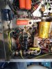
First, I changed the three lug strip bolted to the sidewall of the SA-300 and replaced it with a seven lug strip using the same bolt hole. I reconnected the transformer red/black lead (30v source, though mine reads closer to 60) and reused the diode. Then I attached the 390 ohm resistor and the 10uf 350V cap to ground. Note the long seven lug terminal strip, the 390 ohm resistor and the 10uf cap. The diode is hidden underneath, but you can also see the yellow .1uf film cap I replaced the oversized orange drop with. Sometimes space really does matter. Last to go in were the pots and the resistors to ground.

attachment.php


That left me with the two 10k pots and the two 33k resistors to ground to attend to. Since I had some spare IBAM 10k pots around, I decided to mount the last circuits on a perf board and bolt it to the sidewall. So, I reused the hole that had been used to hold a stop to keep the old 5k bias pot from spinning and attached a three lug strip to anchor the perf board to.

attachment.php


I put it all together, soldered everything up and brought the unit up on the variac. One channel worked like a charm and the other channel wouldn't bias. After moving the perf board I discovered that I'd put it in too tightly and had shorted the pot. With a wiggle I got the second channel to bias, but I wasn't happy to leave well enough alone. I had to fully break what wasn't broken.
While in the process of moving and redrilling the perf board one leg on one of the pots broke off, so I'll have to redo that part.

But it will still look like this. The only difference is that the new perf board will be a little further away from the sidewall that's on the bottom in this photo.

attachment.php


It's tough working in tight spaces.
As Rodney Dangerfield would have said, "It's rough out there; I'll tell ya".
 

Attachments

  • Fisher SA-300splitbias.jpg
    Fisher SA-300splitbias.jpg
    111.4 KB · Views: 62
  • sidefastener.jpg
    sidefastener.jpg
    136 KB · Views: 60
  • bias pots.jpg
    bias pots.jpg
    147.4 KB · Views: 61
Last edited:
Nice looking work!
My amp needs a little more work because the guy before me was a Hack. (If he's out there and reading this he should be ashamed).
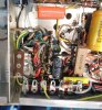
Look at this gloppy mess. He must have used a ton of flux when he desoldered because there's splatter all over the place
IMG_4160_zps6f0603d0.jpg


There are burnt wires, barely completed solder joints...I have to go through this thing from the power cord (which I actually replaced) to the output trannies.

Anyway, because I have to dig so deep to make things pretty again, it doesn't bother me to rip things apart if I have an idea.
I really want to be able to bias and balance this amp without having to take extraordinary measures. So I cut the wires from the hum balance pots, etc, and removed the entire wall (only 3 screws).I found these pots at Mouser and decided to mount them in nearly the same space where the single bias pot was located.

IMG_4181_zps8fd1b977.jpg


This is the framework for what comes next.

IMG_4187_zps2f09e101.jpg


It's back in the chassis and I'm gradually rebuilding the power supply. The two pots will occupy a space slightly larger than the original.

The "erector set" bar will eventually support the potentiometer shafts just inside of the side panel (that's why I used it to space the holes in the drilled wall. To access the bias pot shafts, I will drill two holes in the side panel and pop a few brown plugs in there to cover them up. It will look "Fisher Made".

Next step is to reattach the hum pots and run a red wire to the smoothing cap.

I need a knowledgeable and experienced opinion for the 60uf smoothing cap. I can't find a single section 60uf FP capacitor. But I have a 30-30 @450v/450v and a 20-20-20 @450v fp caps. Is it better to use the 30+30 or 20+20+20, and what's the reason. I can see upsides and downsides for each option, just wondering if I'm missing something.
 
Last edited:
I've used two 30s tied together before with no ill-effects, but I can't say which choice would be best. What are the space issues? Can cap? I know I should know this, but I haven't faced the power supply yet. May have to, still some residual low-level hum in both channels. Also, I'm at the office and can't look right now.

I bet, if you don't want to mess with the power supply values, that you could get a 60uf 500v cap custom made by Tom@hayseedhamfest.

Both mine are replaced, but the replacements are probably 25 years old and I'm going to check them out, and their associated resistors, as I chase down that hum.
 
Last edited:
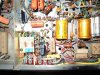
Here's the final shot of the circuitry for the two bias pots. These two pots now each go to one channel's DC balance control.

Bias will be measured by putting the + probe on the tube side of each 10 ohm cathode resistor that's been added, and putting the - probe on the other side of the 10 ohm cathode resistor. Use the bias pot to set the general level to around 70ma. Use that channels DC balance control to get the dissipation consistent between the two EL-34s in each push-pull channel.
I think 70ma is a little hot so I'm going to back off from that level a bit for these Sovteks.

attachment.php


I'm not even going to spark it up and rebias it until I take care of a couple of issues and then I'll chase down that hum. I'm going to replace those Orange Drops connected from the input pot to the first tube. I don't love Orange Drops. Those are the only two directly in the circuit passing AC from what I can see though. The rest are all draining stages to ground.
 

Attachments

  • biasresistors3.jpg
    biasresistors3.jpg
    138.8 KB · Views: 88
Last edited:
Don,
Thanks for the inside view of your amp and work. It's helpful to me because like you, I didn't start out with a virgin amp. Nice looking board too, BTW.

I thought about Hamfest, but I could just as easily re-stuff an old can myself. And honestly, the original calls for 60uf 500v. The voltage at the plates should be just below 400V, and since B+ is usually only a few volts higher, I think the safety margin is still there. Fortunately, I have a cap tester and can test for leakage at real voltages to make sure of what I have.
 
I've tweaked and geeked this thing and wrestled it into stable factory level performance for benchmarking.
You know how we were never particularly happy with how this amp sounded? The changes have eliminated my feeling that there just wasn't enough there there.

I've got it hooked up to the preamp section of my Fisher X-1000 integrated, which means it's essentially hooked up to a Fisher 400-CX preamp with tone control bypass that's been all dcgillespied up. Plus, I'm using the subwoofer in my home office system.

So, this is how it stands:
1. A DC bias control for each channel. This now feeds the DC balance control and provides individual channel bias and DC balance across each push-pull pair.
2. Each EL-34 has a 10 ohm cathode resistor. Now you can measure cathode current across each 10 ohm resistor while adjusting DC bias and balance across tubes, across the pair, and across the quad of output tubes.
3. Screen stability resistors on each output tube.
4. A new .1uf K40Y 400 volt paper-in-oil cap just after each input pot. The input from the preamp goes in series through this cap to the first stage of the amp, so it's critical path for a good cap.
5. New carbon film 1.0 meg resistors in parallel with each output tube coupling cap.
6. A new polarized AC cord.
7. A lighted on/off switch where the AC outlet used to be.
8. This is all on top of updates that were made before.

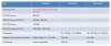
Amp behavior after bias and balance according to procedures but also including measuring across the 10 ohm cathode resistors in series and then from cathode to ground.

attachment.php


I plan to measure this amp for performance and I suspect it will need some tweaks, but its potential is now showing.

 

Attachments

Last edited:
Don,

2 weeks now of being away from home except for a quick turn-around over the weekend, and I'm REALLY JEALOUS of all your fine work! You and Raz have really raised the bar for me!!

Tell me, did that sentence prior to the URL.....did part of that fail to get posted? I'm not quite sure the reference to 'amp behavior' as I don't see a description of such.... unless it's reflected in the contents of the URL...... in which case: Duh! to me!!

Anyway...... one more week 'on the road' and living the Hotel life! Were it not for long days and 'home-work' back in the hotel room, I'd take the amp with me to work on. But, alas.......no time yet.......... NEXT WEEK!!

You guys keep up the good work!!


Tom D.
 
Sorry Tom,
I guess PDF's can't be pasted into the body of the message the way jpegs can. So, I had to go and save the powerpoint contents as a jpg and upload and then paste it into the doc.
 
Don,

I got it! I was looking it over and it looks like you've got the basic parameters pretty well covered. I'll be interested to see how mine stacks up against yours. I've not had time to go back and review some of the posted pics.....but I may hit you up with a phone call in 10 days or so for some further conversation. GREAT job! You and Raz both are doing some incredible things with these amps! I just hope they end up working well enough to merit all the work! TSD
 
Nice work!
Why did you decide to increase the value of the input blocking cap?
After we got my friend's amp working, it kept getting better and better. I think you're going to feel the same way. Something about it sucks you into the music. Have you rolled any tubes yet?
I got delayed and won't be able to get back to it for a week. I'm also still waiting for the last of the replacement components to arrive, hopefully I can knock it out in a day.
 
I figured doubling the input blocking cap might get me a few more cycles of LF response. Plus, I had the caps handy and they fit. Basically, I wanted to remove the orange drops from the signal chain and since the cap is the only thing in the signal chain at that point, I wanted to use a better one.

Back before it redplated, I was using a pair of RCA 12BH7s in the 12AU7 position, but now I'm using RCA clear tops. Next up is RCA black plate 5814s. Then I'll mess with the 12AX7s, but these Mullards were the stock tubes.
The outputs are sovteks and the rectifiers are Mullards.

I used the amp for 10 hours continuously without any blips at all.
 
So after listening to this for a week, I pulled the amp out and put in aside. Last night I connected it again . . . no sound.
While the output tubes were on, the rectifiers were not.
Harrumph!. I put it aside because I've been too busy and barely had the presence of mind to connect it up, but certainly didn't have the presence of mind to go under the chassis again.
 
Don,
Smart move-walk away when you're upset. You'll think clearer in a day or two. Do you have a tube tester? Is it possible the rectifiers got flashed back from a charged first capacitor? Cmax for the 5AR4 is 60uf and that amp pushes it to the limit. Every other amp I've seen uses 40uf after the 5ar4, I figured fisher used 60uf because they were using two 5ar4's. I often wonder if it's worthwhile placing a pair of diodes between the rectifiers and smoothing cap to prevent flashback.
 
Back
Top Bottom