• The move to the new server is done. There are some software and database maintenance updates in process. This has us passing the hat around to help out. We appreciate any donations. Seriously, even a dollar helps. The payment page may be found here - https://www.audiokarma.org/support.html

Fisher SA-300B Set-up and Bias Adj. Question

Don,

I had problems earlier today uploading that diagram. I got the same kind of 'authority' message......so, I'm wondering if AK may have some issues.

I'm going to go look up the X-1000.....but I think it's strictly a 'fixed' bias amp......so that's what confusing. This 300 is 'hybrid'....being both cathode and fixed biased. Weird.....and definitely not as easy to 'set-up' like I'm guessing your X-1000 is. But, I'm going to go 'google' the 1000 and see how that output is set up. I'll give you what ever benefit you may get from my otherwise humble opinion!

WC
 
Don,

Just looked over the X-1000 as best I could. I didn't really find a good copy of the schematic. The one I did find was a low resolution copy.....so, hard to get into some of the detail I would have liked. But, from what I can see.....the cathodes on the outputs are going straight to ground.....and it looks like they use 'fixed' bias...with a resistor to set the negative bias supply voltage (no pot). No doubt a pot could be installed....and it may actually be there and I just couldn't find it on the copy of the diagram I found. I tried to expand it....and it got all 'pixelated' before I could expand it to the point where it was much more than a blur. But, I think the real issue to get a grip on here is the fact that this amp has both: Fixed and cathode bias. That's what's 'different' from the X-1000...which has no cathode resistor or cathode bypass capacitor (R/C network) on the cathodes.....like a typical 'cathode' biased amp! TSD
 
The way I load a graphic is to first create an account with photobucket (photobucket.com).
Once that's done, I create "albums", one for each project ("SA100", "SA300B", "My Dog"). Once in my chosen album, I upload photos from my computer by choosing "upload photo" which allows me to navigate my computer to the photo of my choice in "my documents". I choose, press upload, and it goes up into the "cloud".
Now I need to embed a link in the AK message to the chosen photo in the Photobucket Cloud. While in Photobucket, I make my choice, press "view it" to fill the screen, then copy the URL address.
Back to AK where I want to place the photo, first I make sure I'm logged in. Then I press "Go Advanced" which places me in an edit window with icons at the top of the screen I'm now working in. I press the icon "Insert Image", paste the URL I copied from the photobucket site, and when I press "Preview Post" at the bottom of the screen-the photo is imbedded in my post.

Give it some practice and you'll get it right. But remember, you can only do it from the preview post screen.

Say hello to my little friend!
TobyBoneCloseupcopy_zps04bae99a.jpg
 
Raz,

Would that process not work if the photo were simply taken from the 'My Pictures' file generally associated with most 'windows' based computers? I know Photo-Bucket is a pretty good storage area........particularly if you're concerned about losing pictures on a given hard drive......or if you want to share with other people without sending large files. But, as far as the AK program is concerned, can't you do the same thing by just 'linking' to a photo in your own PC data base? WC
 
OK...... I get it! No URL from which to 'imbed' the image. I've wondered about those larger photos as well. Maybe it's time to go open a photo-bucket account. WC
 
tom. You can use the thumbnails you load to make larger pics.

Right click on the thumbnail, "copy shortcut", then click on the icon with the mountain in it (insert image) mouse over to the highlighted http://, and right click, paste.
 
Larry, is this done after I were to load a pic from my 'pictures' file TO AK ? As it stands now, none of the pics that are simply loaded in my computer have any URL associated with them.
 
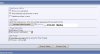
Type in your post. Click on "GO ADVANCED". When it reloads, scroll down to MANAGE ATTACHMENTS. Click on it. Another little box will come up and you can load up to 5 pictures at once. (Click on Browse, click on the pic you want and open it, then load the next till done, then click UPLOAD). When the pics are uploaded it'll show you 5 links. Now close.

Right click on the thumbnail,copy shortcut, and then click on the insert image and rightclick on the highlighted "http://" and Paste.
 
In case my instructions were confusing; I took some screenshots, edited them and uploaded them to AK. They now have a url on the AK server and are kept in YOUR Picture Archive.


attachment.php


Go to "Additional OPTIONS
attachment.php


attachment.php


attachment.php


attachment.php
 

Attachments

  • picture link 1.JPG
    picture link 1.JPG
    19.4 KB · Views: 66
  • picture link 2.JPG
    picture link 2.JPG
    36 KB · Views: 66
  • picture link 3.JPG
    picture link 3.JPG
    64.9 KB · Views: 67
  • picture link 4.JPG
    picture link 4.JPG
    34 KB · Views: 60
  • picture link 5.JPG
    picture link 5.JPG
    47 KB · Views: 59
Finally!!! I think my problem was that I was getting the http:// twice, and it wasn't following the link. But...... looks like I got 'old faithful' here posted. Guess it's time to hit 'submit' and see........... Thanks Larry! TSD


attachment.php
 

Attachments

  • DSC01800 (2).JPG
    DSC01800 (2).JPG
    154 KB · Views: 63
All right. I'm back.
My permissions issue has to do with the hard drive in my iMAC. Even though a recursive permissions update has been done, there's that pesky issue of not being able to answer or view PMS or upload photos on that machine.

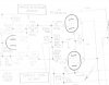
Here's how the fixed bias works on the X-1000. It does have two bias controls and two DC Balance controls.

attachment.php


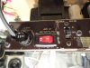
Next we have the switch I put in. A nibbling tool is a wonderful thing.

attachment.php


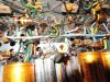
Next are the screen stability resistors. Put in properly this go-around. I've finally got this down. I had to put in a new three lug terminal strip. It's tight under the hood.

attachment.php


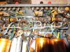
Finally, I went back and re-jumpered pins 1 and 8 on each tube and put a 10 ohm resistor to each side's cathode RC network. I had to put in another five terminal strip to make this work. I always work hard to make the work look good, to have leads that are at 90 degree angles, to keep it neat, but it's not looking as good in the photos as it looks on my bench.

attachment.php


Tomorrow: Turn-up.
 

Attachments

  • X_1000_outputs.jpg
    X_1000_outputs.jpg
    48.4 KB · Views: 74
  • switch.jpg
    switch.jpg
    70.5 KB · Views: 74
  • screenresistors.jpg
    screenresistors.jpg
    133.5 KB · Views: 75
  • biasresistors.jpg
    biasresistors.jpg
    132.1 KB · Views: 74
Last edited:
Finally!!! I think my problem was that I was getting the http:// twice, and it wasn't following the link. But...... looks like I got 'old faithful' here posted. Guess it's time to hit 'submit' and see........... Thanks Larry! TSD

That's it Tom! Please tell me that this is the hog that was in the workroom when i was over last. Looks a lot better than I saw it last!

Larry
 
Hey man,
I like the work you did under the hood! Nice job on the power switch too. But please, turn the fuse holder cap right side up cause it really detracts from the amp, whatever comes just before "total abomination".

I can't zoom in to check the details, but is the brown wire (in the brown/black wire twist) next to the hexagonal post frayed or otherwise damaged? From my vantage point it may be close to an adjacent terminal and I'm concerned some unexpected damage may occur.

I just finished dinner and am going to begin work on my test sockets. I don't want to begin any work under the hood until I have some accurate measurements. My SA300 has balls but lacks the finesse of my SA100, I want to see why before I start swapping tubes and capacitors.

Seriously though, your work is nice. Congrats on a job well done.
 
Don,

Nice work! I'll be interested to see how this works out once you put it into service. BTW, what will you be driving it with, and in to in the way of speakers? I'm just curious as I'm wondering how you're going to react to it vs. what ever was in there previously?

Raz, I'll be interested in hearing what you find with yours as well. Your comment about it's power surprises me. While my SA100 has been EFB's......it's still an EL84 amp and should be now where near the performance that the EL34 amp could produce. Yet, I dare say my 100 would currently outperform my 300....which REALLY concerns me! I love Don's work regarding the hook-ups to analyze the amp. But, I think your diagnostics regarding performance will be helpful to me in order to get my amp performing like it should.

I'm a few weeks away from doing any more work on my 300. I've got a 3-week consulting project about to begin on Monday......and will be out of town and out of state. So, my next few weekends (including this one) are more about what's needed around here vs playing with my toys.

Larry, I got that bike that was in the house OUT a few weeks ago. Did quite a bit of work to it.....carbs rebuilt, full ignition service, overhauled front brake caliper and master cylinder, valve adjustment, clutch adjustment, oil change, a lot of electrical connections had to be re-done in order to get all the electrical 'stuff' to work properly....signals, lights, horn, etc. Bottom line is that I rode it around the neighborhood....it's running well......and now ready for the auction block! The HD in the picture is in my trailer.....and it too needs to be on the auction block! The HD is a beast! Wish I could find a good home for it McSoon! I've also got to sell my BMW R1100RS....which pains me.....but, hey.......time for it to move on!! If you know any biker looking for a bike.........let me know!!

Later,

WC
 
DAMN! If I had the $$$ floating around, I'd take that Bimmer in a Heartbeat. But I'd have to hide it in a storage unit to keep from SWMBO! I really can't dodge Cast Iron Frying pans all that well anymore.
 
I took the first two sockets for a spin tonight. That's the millivolts dropped across a 1 ohm 1% resistor within each socket.
Pretty close....
More tomorrow

IMG_4148_zps25d1d412.jpg
 
Last edited:
Raz,

Just curious, did you 'check' your 1 ohm resistor for variance? I know you don't want to be re-building these gems......and they look very nice BTW......but I was wondering if the variance on a 1 ohm resistor was such that the 'accuracy' of the number might be better across a 10 ohm resistor? I think I read that some place......and it's stuck in my head......and I'm just not really sure. So, you can tell me........if off by ie 2% on a 1 ohm resistor.........is the 'reading' on your DVM going to be more or less accurate than if off by the same 2% on a 10 ohm resistor? One other thing.....did you 'swap' your probes to see if the readings stayed the same, or if there was any kind of change that might indicate some kind of variance in the resistors? Those are some first-class meters I might add!! Very nice work!! Tom D.
 
Good questions.
I did check the resistors (all 1% precision wirewound) from a lot of 20 purchased from the same batch. They all tested 1.1 ohms at the resistor bodies using the same meter and probes, which means the probes and their wires became part of the measurement.

At such a low resistance (1 ohm), the only way to select exact matches is to string 10 or more together in series, connect them to a regulated power supply and measure the voltage drop across each resistor. Using Ohm's law, the exact resistance of each resistor can be calculated from the individual voltage drops measured.

But given the inherent resistance in the probe wires, the test lead wires and the meter itself, I felt that laboratory precision was unnecessary for this test (I bought more than 4 sets of sockets just in case). because I will be measuring the voltage drop at the amplifier's working voltage-not the operating voltage of any meter. And keep in mind, these are all 1% precision resisters from the same batch, as long as they are all within tolerance and remain there, I think we're fine.

So to keep the above noted factors equal between test socket sets, I used the same lengths of wire from socket to plug to minimize these issues.

Now..the real reason I wasn't going for "laboratory precision" while measuring and calculating the current passing through each tube's cathode was because I only wanted to see if the tubes in each pair were more or less equal and passing a current that was in the same area code. When I use four meters, I'll know if I have a matched quad or if it's necessary to split the bias supply into left and right channels.


Keep in mind-The Fisher instructions are to adjust bias to 7.8 vdc at pin 8 of each tube. That's pretty general, especially with an allowable range of 7.3vdc to 8.3vdc. I'd rather do this with a 1 ohm resistor in series than 10ohms. Because I used stackable plugs, I can check each tube individually, which might indicate an internal issue if the voltage measured was higher on one channel or tube. Another reason I was waiting to see if splitting the bias supply was necessary.

Now, for DC Balance-
I can place a third meter from positive to positive on each meter's positive plug (another reason why I used stackable plugs) so that I can accurately adjust the DC balance to a minimum value while keeping an eye on the total bias currents passing through each tube in that pair. If I'm interested in DC balance alone I can simply connect the common (blue) wires together (the great thing about stackable plugs) and use the two red wires with one meter as I adjust the DC balance to zero voltage. In this (preferred) manner, the cathodes from each tube in the tested channel are tied together through 2 ohms (1 ohm within each socket) then back to the common cathode resistor with capacitor bypass to ground. Again, I thought it was better to add 2 ohms instead of 20 to this circuit.

I see your point, but I thought even if I used 10% resistors, adding 2.2 ohms to the circuit was better than adding 22 ohms. Not that I think any of it would really matter anyway.

To answer another point you raised, I have not yet swapped sockets and meters at the same tube socket positions to verify accuracy....but I will. If I note anything significant-I'll add a +/- notation to each test socket.

I want to make one thing clear-the reason I thought using external test sockets was the better way to go was the flexibility they afford and that I can test and adjust this or another amp's DC balance after it has warmed up without having to remove the bottom cover, etc.. I can run the amp for an hour with the tubes in their test sockets, each socket connected to it's own meter and jumper the plugs at each meter thus removing the meter from the circuit (final reason for using stackable plugs). After the amp has warmed up, I can pull the meter bypass jumpers and set the bias voltage, quiescent current and DC balance. And I don't have to move around probes, keep my eyes on more than one place, or otherwise risk an explosion.

How simple is that?

One more thing-I decided to put the 1 ohm resistors in the test sockets to measure voltage drops rather than breaking the circuit to measure the current through a meter after I read about the possibility of causing an amp to oscillate using the latter method.

Last point--some people adjust bias and balance very successfully by ear. What does that say?

 
I've heard music again out of mine.
I put in some Sovtek EL-34s I've been saving as test tubes. I've played some with the bias and balance, but have to go back and do it methodically, not ad-hoc.
 
Back
Top Bottom