

You are using an out of date browser. It may not display this or other websites correctly.
You should upgrade or use an alternative browser.
You should upgrade or use an alternative browser.
Fisher X-1000 integrated - Welcome
- Thread starter audiodon
- Start date

Damn Don!! And that was sitting on the Executive I have my eye on (I can dream!)

hotroady
Well-Known Member
Very nice, I love those X-1000's its good to see its in capable hands!
I had thought about getting one of those as a few came up which I had an opportunity to get, but I held off as I kind of had my mind set on getting a Sansui AU-111. Then a few weeks ago a clean AU-111 came up but I was unable to swing it, I should have snagged that X-1000 back when I had the chance. Any ideas on which of the two would be the better sounding amp?
I would like a AU-111, too. The Fisher with Telefunken 12ax7 long smooth or rib plates sounds wonderful. It's extra 15w per channel sure came in handy for me.
I run Martin Logan Clarity speakers with the X-1000. The larger the 'stats, the more power hungry they become. I fitted the ML's with French designed 12lb, 8in drivers with 4in voice coils. I have to crank the throttle up about a third to match the output, now. 33w, 42w amps don't quite cut it. Overall the ML'S sound more dynamic with the added power. Bass from 45hz-to the 450 crossover is now everything it should be. Where it was thin before, it has tractor like torque, now. Voicing so much better, also. Great synergy!:thmbsp:

Nice Score! Theres a K1000 amp on Ebay right now, whats the difference between it and a SA1000??? Any?

audiodon
Addicted Member
Never heard of a K-1000 before now.
http://itishifi.blogspot.com/2012/11/the-fisher-k-1000-stratakit.html
http://itishifi.blogspot.com/2012/11/the-fisher-k-1000-stratakit.html

Hiya,
Only 329.50 .. I will take ten please ???

EDIT: PS .. if you are bored you can take a look at the guy/gals other stuff he is offering that I am guessing was from the same Estate and be prepared to be sad/jealous .. guy/gal hit the mother load with someone's TOTL Fisher setup.
Frannie
Only 329.50 .. I will take ten please ???
EDIT: PS .. if you are bored you can take a look at the guy/gals other stuff he is offering that I am guessing was from the same Estate and be prepared to be sad/jealous .. guy/gal hit the mother load with someone's TOTL Fisher setup.
Frannie
Last edited:
I just double checked, yes there is a K1000...looks alot like the SA1000. Hybrid?

It's the kit version of the SA-1000.
Thanks Fisherdude, where did you find that info? I never heard of one either till I stumbled across it..looks good though Love the tan based tubes.

Never heard of a K-1000 before now.
http://itishifi.blogspot.com/2012/11/the-fisher-k-1000-stratakit.html
I think this post points out that the K is the kit version.
I think any of the Fishers that start with the K might be Fishers way to identify that it was a Kit version. My Fisher is a Kx200 which is a kit version. One thing good it was easier for me to work on than a more loaded down amp as their is much less stuff to weed thru, (and less to go wrong).
audiodon
Addicted Member
Dave and I are wondering how many could apply this final check and stress test information to their own X-1000s.
This would only be relevant to EL-34 based Fishers, and in particular to X-1000s, and perhaps somewhat to SA-300s. The testing setup in general can apply more broadly, but, unlike Dave's threads on the Fisher 400s, where most updates can apply broadly across the product line of that era, this would have narrow application.
This would only be relevant to EL-34 based Fishers, and in particular to X-1000s, and perhaps somewhat to SA-300s. The testing setup in general can apply more broadly, but, unlike Dave's threads on the Fisher 400s, where most updates can apply broadly across the product line of that era, this would have narrow application.
Last edited:

Restoration of Restorations
It's always interesting if not challenging to work on a piece of equipment that has obviously seen many work benches before your own. Careful study allows the different approaches and skill levels to all reveal themselves much like layers of an archaeological dig might turn up. With vintage gear, it's all made all the more interesting when the subject is as complex as a Fisher X-1000.
For the less informed Fisher enthusiast (like I was), this is a unit that Fisher even threw in the kitchen sink on, containing just about every feature, indicator light, gizmo and doodad that Fisher engineers could conjure up at the time. Remote volume control option, remote control of the optional SpaceXpander unit, three options for center channel outputs with front panel level control, active phase reversal circuitry, and the list goes on. These plus all the usual litany of Fisher knobs and controls provides more setting options than Baskin-Robbins has flavors of ice cream. 100 watts of fixed bias EL34 power with all these bells and whistles shoehorned into an integrated amplifier no bigger than the usual Fisher integrated offering. At the time, this baby had enough power to drive any locomotive right off its tracks. It is truly an engineering feat to behold, heavy and densely packed enough to form a black hole!
In its most basic form, the X-1000 has two power amplifiers that -- except for the non-UL OPTs -- closely resemble two Dynaco MK IIs on a single chassis, powered by the usual Fisher solid state power supply design. Add to that a control section that is virtually cut right out of a 400c preamplifier, and the standard Fisher low level preamplifier circuits (with extra EQ positions and output level controls provided), and you end up with an X-1000.
This example arrived obviously broken, and with a broken tube as well. The unit had been previously modified with separate cathode resistors and test points for more accurate bias adjustments, but one of the cathode resistors had clearly gone beyond critical mass to where no man has gone before. While the nearby blackened components and chassis area were left to tell the tale, that sucker had otherwise vaporized itself into oblivion. Two sets of output tubes were provided -- a set of used Mullards, and a rather new set of Sovtek EL34s. Wouldn't you know it, it was one of the Mullards that broke during shipment. With this, I took the next two days to give the unit a close physical examination (no power), study the extensive schematics that Don had provided, and developed a plan.
One of the first steps was to give all the tubes a thorough evaluation. As luck would have it, it was probably a good thing that it was one of the Mullards that broke, because of the remaining three, only one was considered usable for service. The other two had very poor power output capability (<40%), meaning the odds were that the broken one likely wouldn't have fared much better if it had been able to retain its vacuum. On the other hand, the Sovteks were all usable enough (two even approaching true NOS capability), so if one had to go, it was actually best that it wasn't one of the Sovteks in his case. All the small signal tubes were more than capable for proper performance testing of the unit.
When I receive a unit, I always look at it with two primary concerns in mind. (1) That the unit is operating to its fullest potential, and (2) What possibilities exists to make the unit more usable in today's audio environment. After studying the schematics, I made a list of options I presented to Don for him to consider.
This unit avoids many of the compromises that I addressed in my recent 400 threads, but still has some issues of concerns. Like the 400, the Tape Output signals provided at the rear jacks for tape or external signal processing equipment are phase inverted from the source signals provided to the unit. Also, the unit as a whole inverts signal phase. Many listeners are sensitive to reversed phase presentations. Then there are the various filter circuits that the signal goes through whether the filter is activated or not, or the permanent LF filter, etc. Finally, there is also the positively goofy, uniquely Fisher "feature" of that crazy bleeder circuit between the Tape Monitor function, and the Aux 1 input on this unit as well. (What the heck were they thinking?) For today's critical listener, these features typically fall through the basement floor in terms of importance, while phase inverting issues become paramount. Their removal/correction not only improves the sonic presentation, but also usually makes room for potentially more useful features. A list of possibilities was sent to Don. As discussions of these options ensued, I set about starting repair of the unit.
The original problem of LF oscillation was traced to an undersized current limiter that had been installed somewhere along the way, that was fading in and out of limiting as the AC line level was increased. To get to it, and do a proper job of correcting that really required removal of the rear panel, since even Munchkins are not small enough to service that area. This was made worse by a large green wire ground power cord that had been fitted at some point as well. As a result, the AC wiring in the area looked pretty beat up with more skirmishes from a soldering gun tip than the terminals themselves received. It's a good thing I removed the panel too, as the power wire to the rear receptacles was found broken off, as was the ground lead for the right channel low level inputs -- all apparently from previous efforts in the area. And of course the bleed circuits for the Tape Monitor/Aux 1 circuits were located back there as well. So, off it came not only to fix the obvious problems, but also with an eye to address any of the changes necessary in that area to facilitate the modifications we had agreed to pursue.
Other areas of concern were the previous incorrect installation of screen stability resistors, of course the blown up cathode resistor, and the fact that the new power cord had not been connected for lowest noise. As of today, all of these issues have now been fixed/addressed/corrected, so that the next step will be to conduct a full battery of tests on the (basically) stock unit, for establishing a bench mark to judge any modifications against.
Next time, I will present the performance findings of the stock unit. Armed with that knowledge, then best determinations can be made as to what modifications would offer the most worthwhile improvements over the stock design.
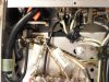
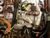
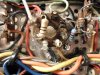
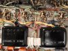
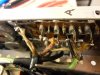
For now, I failed to take any pics of what the unit looked like when I received it, but here are a few pics of the repair work that's been done since then to bring the unit to the point where measurements can now be made:
1. Fixed/replaced/reconfigured AC power wiring.
2. Relocated In-rush Current Limiter for easier serviceability.
3. Replaced cathode resistor. Despite best efforts to clean the area, evidence remains of the nuclear event.
4. The screen stability resistors and wiring were all removed, and reinstalled as shown.
5. The wacky Tape Monitor/Aux1 bleed circuit components have vanished.
What a journey this one's gonna be!
Dave
It's always interesting if not challenging to work on a piece of equipment that has obviously seen many work benches before your own. Careful study allows the different approaches and skill levels to all reveal themselves much like layers of an archaeological dig might turn up. With vintage gear, it's all made all the more interesting when the subject is as complex as a Fisher X-1000.
For the less informed Fisher enthusiast (like I was), this is a unit that Fisher even threw in the kitchen sink on, containing just about every feature, indicator light, gizmo and doodad that Fisher engineers could conjure up at the time. Remote volume control option, remote control of the optional SpaceXpander unit, three options for center channel outputs with front panel level control, active phase reversal circuitry, and the list goes on. These plus all the usual litany of Fisher knobs and controls provides more setting options than Baskin-Robbins has flavors of ice cream. 100 watts of fixed bias EL34 power with all these bells and whistles shoehorned into an integrated amplifier no bigger than the usual Fisher integrated offering. At the time, this baby had enough power to drive any locomotive right off its tracks. It is truly an engineering feat to behold, heavy and densely packed enough to form a black hole!
In its most basic form, the X-1000 has two power amplifiers that -- except for the non-UL OPTs -- closely resemble two Dynaco MK IIs on a single chassis, powered by the usual Fisher solid state power supply design. Add to that a control section that is virtually cut right out of a 400c preamplifier, and the standard Fisher low level preamplifier circuits (with extra EQ positions and output level controls provided), and you end up with an X-1000.
This example arrived obviously broken, and with a broken tube as well. The unit had been previously modified with separate cathode resistors and test points for more accurate bias adjustments, but one of the cathode resistors had clearly gone beyond critical mass to where no man has gone before. While the nearby blackened components and chassis area were left to tell the tale, that sucker had otherwise vaporized itself into oblivion. Two sets of output tubes were provided -- a set of used Mullards, and a rather new set of Sovtek EL34s. Wouldn't you know it, it was one of the Mullards that broke during shipment. With this, I took the next two days to give the unit a close physical examination (no power), study the extensive schematics that Don had provided, and developed a plan.
One of the first steps was to give all the tubes a thorough evaluation. As luck would have it, it was probably a good thing that it was one of the Mullards that broke, because of the remaining three, only one was considered usable for service. The other two had very poor power output capability (<40%), meaning the odds were that the broken one likely wouldn't have fared much better if it had been able to retain its vacuum. On the other hand, the Sovteks were all usable enough (two even approaching true NOS capability), so if one had to go, it was actually best that it wasn't one of the Sovteks in his case. All the small signal tubes were more than capable for proper performance testing of the unit.
When I receive a unit, I always look at it with two primary concerns in mind. (1) That the unit is operating to its fullest potential, and (2) What possibilities exists to make the unit more usable in today's audio environment. After studying the schematics, I made a list of options I presented to Don for him to consider.
This unit avoids many of the compromises that I addressed in my recent 400 threads, but still has some issues of concerns. Like the 400, the Tape Output signals provided at the rear jacks for tape or external signal processing equipment are phase inverted from the source signals provided to the unit. Also, the unit as a whole inverts signal phase. Many listeners are sensitive to reversed phase presentations. Then there are the various filter circuits that the signal goes through whether the filter is activated or not, or the permanent LF filter, etc. Finally, there is also the positively goofy, uniquely Fisher "feature" of that crazy bleeder circuit between the Tape Monitor function, and the Aux 1 input on this unit as well. (What the heck were they thinking?) For today's critical listener, these features typically fall through the basement floor in terms of importance, while phase inverting issues become paramount. Their removal/correction not only improves the sonic presentation, but also usually makes room for potentially more useful features. A list of possibilities was sent to Don. As discussions of these options ensued, I set about starting repair of the unit.
The original problem of LF oscillation was traced to an undersized current limiter that had been installed somewhere along the way, that was fading in and out of limiting as the AC line level was increased. To get to it, and do a proper job of correcting that really required removal of the rear panel, since even Munchkins are not small enough to service that area. This was made worse by a large green wire ground power cord that had been fitted at some point as well. As a result, the AC wiring in the area looked pretty beat up with more skirmishes from a soldering gun tip than the terminals themselves received. It's a good thing I removed the panel too, as the power wire to the rear receptacles was found broken off, as was the ground lead for the right channel low level inputs -- all apparently from previous efforts in the area. And of course the bleed circuits for the Tape Monitor/Aux 1 circuits were located back there as well. So, off it came not only to fix the obvious problems, but also with an eye to address any of the changes necessary in that area to facilitate the modifications we had agreed to pursue.
Other areas of concern were the previous incorrect installation of screen stability resistors, of course the blown up cathode resistor, and the fact that the new power cord had not been connected for lowest noise. As of today, all of these issues have now been fixed/addressed/corrected, so that the next step will be to conduct a full battery of tests on the (basically) stock unit, for establishing a bench mark to judge any modifications against.
Next time, I will present the performance findings of the stock unit. Armed with that knowledge, then best determinations can be made as to what modifications would offer the most worthwhile improvements over the stock design.
For now, I failed to take any pics of what the unit looked like when I received it, but here are a few pics of the repair work that's been done since then to bring the unit to the point where measurements can now be made:
1. Fixed/replaced/reconfigured AC power wiring.
2. Relocated In-rush Current Limiter for easier serviceability.
3. Replaced cathode resistor. Despite best efforts to clean the area, evidence remains of the nuclear event.
4. The screen stability resistors and wiring were all removed, and reinstalled as shown.
5. The wacky Tape Monitor/Aux1 bleed circuit components have vanished.
What a journey this one's gonna be!
Dave
Attachments
audiodon
Addicted Member
My education continues.
This one had some aspects to it that have eluded my solutions.
I'd done a whole thread on motorboating, yet it never occurred to me that a thermister had current ratings that might be exceeded the way it was on this amp. Sometimes it takes another set of eyes to provide that fresh approach that makes the difference between the unit being good and being great.
I'm very happy that it will get a full tune up and performance will be properly blueprinted.
This one had some aspects to it that have eluded my solutions.
I'd done a whole thread on motorboating, yet it never occurred to me that a thermister had current ratings that might be exceeded the way it was on this amp. Sometimes it takes another set of eyes to provide that fresh approach that makes the difference between the unit being good and being great.
I'm very happy that it will get a full tune up and performance will be properly blueprinted.
Last edited:
Well, hold the phone -- we're not out of the woods yet on motor boating. Partially out, but not all the way. It appears that there is at least another issue relating to this problem, and it's notable enough that I couldn't even get to run any tests yet.
B+ is now stable, and channel B initially appears to be stable, but I couldn't fully check it out because channel A is a completely different story. LF instability can be easily triggered, if not self triggering. Since Channel B didn't appear to have the problem, that typically rules out the power supply. Hummmmm......Assuming no gross inductance problems with the OPT, I smell coupling/feedback problems.
Stay tuned. I'll let you know what I find.......
Dave
B+ is now stable, and channel B initially appears to be stable, but I couldn't fully check it out because channel A is a completely different story. LF instability can be easily triggered, if not self triggering. Since Channel B didn't appear to have the problem, that typically rules out the power supply. Hummmmm......Assuming no gross inductance problems with the OPT, I smell coupling/feedback problems.
Stay tuned. I'll let you know what I find.......
Dave
Ah - found the little bugger, but out of time for the moment. Update later tonight.
Dave
Dave
The mortal enemy of any feedback amplifier (which Fisher amplifiers always are) is phase shift. Too much of it and what WAS negative feedback can become POSITIVE feedback. Invariably, this occurs at frequencies above and below the audio spectrum. The typical approach to dealing with this problem is to make sure that the response of the basic amplifying circuit is flat to within an octave above and below the audio frequency spectrum, and then gradually roll off the response of the circuit above and below those points. That way, when the phase shift does reach 180 degrees of shift, the loop gain has dropped below unity, and the circuit cannot oscillate.
To accomplish this, you will often see small caps between the signal path and ground (to roll off the high end), and reduced or specifically sized coupling or bypass caps to roll off the low end response -- all to maintain both high and low frequency stability. This is why I mentioned possible coupling problems as a cause of this issue a couple of posts back.
In the X-1000, Fisher chose to address the low frequency roll off requirements in the (seemingly) complex coupling networks that exist between the phase inverter and the output stage. The components in these networks all play a critical roll in effectively providing DC coupling between the inverter and output stages, yet rolling off the ultra lowest frequencies to maintain stability, while still allowing all the frequencies of the audio spectrum to pass through unattenuated. These networks generally work quite will at what they're supposed to do -- when they're in the circuit. In Channel A however, the components had been installed in such a way that these networks to both output tubes were effectively bypassed. Ergo, with no attenuation of the very lowest frequencies, that produced the socially unacceptable performance (i.e. motor boating) of channel A.
So there were actually two problems causing the motor boating issue. I had first suggested the possibility of current limiter problems in post #21 of the thread specifically relating to that problem with this amplifier. Others had suggested bad coupling caps. While the problem specifically in channel A was technically coupling cap related, it wasn't due to bad caps, but rather, effectively missing caps.
Channel A's instability issues ultimately caused it to draw significantly more current when it would oscillate due to this issue, causing more current to be drawn through the undersized current limiter, exacerbating the problem with it. But with both problems present at the same time, it effectively allowed each problem to hide somewhat behind the other, making diagnosis much more difficult. By ol' Sherlock's definition then, it was truly a two pipe problem!
Barring no other surprises then, I should have this issue wrapped up this evening, so that testing can hopefully start tomorrow.
Dave
To accomplish this, you will often see small caps between the signal path and ground (to roll off the high end), and reduced or specifically sized coupling or bypass caps to roll off the low end response -- all to maintain both high and low frequency stability. This is why I mentioned possible coupling problems as a cause of this issue a couple of posts back.
In the X-1000, Fisher chose to address the low frequency roll off requirements in the (seemingly) complex coupling networks that exist between the phase inverter and the output stage. The components in these networks all play a critical roll in effectively providing DC coupling between the inverter and output stages, yet rolling off the ultra lowest frequencies to maintain stability, while still allowing all the frequencies of the audio spectrum to pass through unattenuated. These networks generally work quite will at what they're supposed to do -- when they're in the circuit. In Channel A however, the components had been installed in such a way that these networks to both output tubes were effectively bypassed. Ergo, with no attenuation of the very lowest frequencies, that produced the socially unacceptable performance (i.e. motor boating) of channel A.
So there were actually two problems causing the motor boating issue. I had first suggested the possibility of current limiter problems in post #21 of the thread specifically relating to that problem with this amplifier. Others had suggested bad coupling caps. While the problem specifically in channel A was technically coupling cap related, it wasn't due to bad caps, but rather, effectively missing caps.
Channel A's instability issues ultimately caused it to draw significantly more current when it would oscillate due to this issue, causing more current to be drawn through the undersized current limiter, exacerbating the problem with it. But with both problems present at the same time, it effectively allowed each problem to hide somewhat behind the other, making diagnosis much more difficult. By ol' Sherlock's definition then, it was truly a two pipe problem!
Barring no other surprises then, I should have this issue wrapped up this evening, so that testing can hopefully start tomorrow.
Dave