• The move to the new server is done. There are some software and database maintenance updates in process. This has us passing the hat around to help out. We appreciate any donations. Seriously, even a dollar helps. The payment page may be found here - https://www.audiokarma.org/support.html

Fisher X-1000 integrated - Welcome

Another Tug on the Thread

With proper output wiring and the power amplifier driver section coupling caps all disengaged from each other -- as well as performing a thorough going through the power amplifier section yet again, the power amplifiers were checked again for response to see if these measures would help the ailing HF response of these units. This time, it was super easy to perform these tests, since the shorting straps coupling the output of the control sections to the power amplifier inputs could simply be removed, and the signal inject at that point.

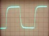
Unfortunately, while the response did improve somewhat based on measurements, there was not enough material improvement to produce anywhere near the desired response. As a result, display of a 10 kHz square wave changed little from the original results recorded. It must be assumed therefore, that the results are a product of the desired engineering outcome of the design -- which is not particularly surprising. This type of transient and frequency response is synonymous with the Fisher sound, lending to that lush, pleasant sound that is very listenable, but lacking in transient detail.

I make no judgement of enjoyment that comes from the Fisher sound, as it really is very enjoyable to listen to. In view of the harshness sometimes associated with SS gear, it is a welcomed relief to be sure. However, as with most things in life, the answer is in the middle, such that replacing the harshness of SS sound with the lushness of the Fisher sound could be viewed as going from one extreme, to the other. In the process, the qualities of sound that can cause you to really become engaged with it can be missed with either approach. My efforts here are to maintain all the virtues that vacuum tube amplification provides, while still striving for accurate reproduction of those detail elements in recorded sound that help to provide a realism that would otherwise not be possible.

Pursuing that goal then will require a complete look at the power amplifiers to see what can be done to produce a wider, flatter frequency response from them, while still maintaining a high degree of stability and low distortion, which is so necessary for high performance measurements to turn into high performance sonic results. It simply does no good to have a high performance line stage/control section, if the power amplifier section is simply going to mask all the gains in performance achieved there.

For now however, some listening tests will be done comparing the two channels of the line amp/control section, and then the effort will continue to finish out the line/control section completely in both channels. Once that is finished, then the power amplifiers can be tackled in earnest.

Pics:

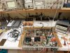
1. All wired up (again) for power amplifier measurements. This time however, the test signal can be injected directly into the power amplifiers via the new Power Amplifier Input jacks on the rear panel.

2. Not much change from before. The 10 kHz waveform is surely nice and smooth, resulting in little listener fatigue, but the detail transient information of today's best source material is simply not going to pass very well through these amplifiers as designed.

With these tests then, the final road map has been established to fully address the performance possibilities of the X-1000's design. Since all the stock circuits perform to a similar level of performance, it is little wonder then that they will all end up being addressed to make the unit be all it can be. Such is usually the case, where if enhanced performance is the goal, every point of circuit design needs to be reviewed, as addressing just one point in the signal path still leaves performance largely determined by the remainder of the design. As so it is here as well. More to follow......

Dave
 

Attachments

  • X-1000 Power Amplifier Retest 002.jpg
    X-1000 Power Amplifier Retest 002.jpg
    127.9 KB · Views: 46
  • X-1000 Power Amplifier Retest 001.jpg
    X-1000 Power Amplifier Retest 001.jpg
    43.5 KB · Views: 28
Well, that would be a pretty good shape if this were a roller coaster track instead of a 10k square wave.
It will be interesting to see if it's the circuitry or the transformers or a combination of both that keep this in the "narrowband" category.
I suspect it may have been a deliberate design effort they took pride in.

attachment.php
 

Attachments

  • rollercoaster.jpg
    rollercoaster.jpg
    99.2 KB · Views: 152
Last edited:
I agree completely Don. Particularly so, because the square waves produced from the stock X-1000 power amplifiers is so similar to that produced from the stock power amplifiers originally in my 400 receiver.

Understand too that in the mid and late 50's, designing stable feedback amplifiers was going through radical changes seemingly overnight. So many of the mid-50s feedback amplifiers that touted a frequency response beyond the moon were also properly blamed for being so unstable as to rather regularly burn out tweeter elements as well. In response, amplifier manufacturers quickly reigned in frequency response specifications, in favor of more stable performance, albeit with significantly lower response specifications. Fisher themselves when through their own stability problems with their famous boxcar amplifiers, so they had been "burned" by the issue as well. As a result -- and is so often the case -- they went clear the other direction with notably reduced response characteristics, resulting in what is well known as the Fisher sound.

The bottom line is, that back in the day, engineers really struggled with producing good stability, good frequency response, and good distortion characteristics all at the same time. All to often, one of these parameters dominated their design criteria, with the sonic character of this unbalanced approach being the result. Some time ago, I developed a much more balanced set of goals to strive for in all of these areas, that results in a very transparent presentation sonically, as well as excellent measured performance, so that you no longer hear the amplifier per se, but the music presentation for what it is instead.

It is the same approach I will apply to the power amplifiers of the X-1000 as well.

Dave
 
The work bench is going to have to be cleaned up before I can move the X-1000 back over there to finish installing the rest of Channel B's control section circuits. So while it is still over on the test bench, I ran some quick tests on the OPT response, and the effects that each of the stock HF stability networks has on circuit response.

Those tests indicate that the response of the OPTs are just fine, allowing an uncompensated HF response to over 100 kHz within +0/-.5 db when the NFB loop is closed. For the amount of FB employed (~19 db), that level of response should allow for a compensated frequency response in the finished product that is far greater than the stock design is delivering, with excellent stability and distortion performance as well. Therefore, it appears that the culprit producing the poor response in the stock design are HF compensation networks that were designed with a very heavy hand -- using more of a brute force approach than a precise calculated one.

This gives me something to chew on while finishing up the control section, but suggests that there can be significant sonic improvement available in the power amplifier section as well.

Dave
 
Update, Observations, and Other Stuff

Since the past few days have been primarily spent with family, progress has been temporarily interrupted -- although I have still been able to do some extended listening to the X-1000 in its current state of (dis)repair. To recap, when I left off: Channel A is still (and intentionally) basically stock from input to output, while channel B is operating with the entirely new line amplifier/control section design. The highlights of the changes to Channel B at this point then includes:

1. Revising the Tape Monitor circuit to eliminate the Aux 1/Tape Monitor bleed circuit, and placing the Tape Monitor switch directly at the output of the mode switch. This allows the Aux 1 and Tape Monitor inputs to operate as two separate inputs, while equalizing the gain and eliminating the phase reversal that took place between the Tape Monitor and all other line level inputs in the original design.

2. Installing a new single ECC82 based line stage amplifier (ultimately one for each channel). This design mimics the gain of the original X-1000 line stages, while eliminating all the built in filters employed in the original design. The new design also eliminates spreading the line amplification process out between various tubes as was done in the original design, containing all the necessary amplification within one dual triode tube. Finally, the new line amplifier eliminates the use of the 7247 tube used in the original design.

3. Installing a new buffer output stage at the output of the line amplifier/control section, before the input to the power amplifier section proper. This then allowed for reconfiguring the old Reverb jacks into new Preamp Output/Power Amp Input jacks.

At this point, no changes have been made to either power amplifier section, so that the listening tests could spotlight changes made to the line amp/control section alone. The sonic observations between the two channels then include:

A. The gain of the original and new line amplifier design are so closely matched, that the balance control remained centered, and the sound stage was still very clearly and equally presented across the channels. This means that when finished, the redesigned X-1000 will display the same volume control action and sensitivity as that of the original design did.

B. The new design is notably quieter with respect to the hiss and circuit noise of the original design with no input and the volume advanced to full. Noise from the new design is cut to about one third of the original design, but will be accurately determined when final measurements are made. Since the filter circuits have been removed in channel B, the reduction in noise was to be expected. Only the necessary gain for basic amplification is now used, and the extra amplification necessary for the filter circuits to operate has been eliminated.

C. This unit has a wicked basic hum level with the volume control at minimum (at least to me it does through my Cornwalls), which is equal and common to both channels. It roundly smacks of power supply hum (120 Hz), so attention to filtering and potential ground loops will now be the order of the day, and cause a slight detour to troubleshoot and determine just how involved it will be to get a handle on/correct this issue.

Actually, this is not all that uncommon of a problem with the highest power integrated amplifiers, since big power supplies, high power output amplifiers, and sensitive audio circuits don't really mix well together. That's why the whole idea of separate preamps and power amps was born in the first place. Marrying all of these circuits together on one chassis then is bound to create design problems -- or some level of compromise at the very least.

To be honest, at my listening position the hum is basically inaudible, but anywhere near the speaker boards, it is painfully obvious. This is as against my modified 400 receiver, where you basically have to look at the receiver to see if it is on, since there is no sound whatsoever through the Cornwalls when the volume control is at minimum with that unit.

D. Sonically, the sound is more balanced across the audio spectrum, eliminating a mild upper midrange bloom. Bass is not any deeper, but is more clearly defined. On the high end, percussive instruments (wood blocks, sand blocks, maracas, etc) are clearly present, where they are not in the stock channel. When actively listening for them in Channel A, they are there -- but only because you know to listen for them. In Channel B, they take their place for you to hear on the first listen. Understand that Channel B is in no way brighter sounding than Channel A, it's just that small detail is now clearly present in Channel B, that is somewhat lost in the stock channel by comparison. These observations are made with the tone controls still active in both channels, since the bypass feature has not been installed yet in Channel B.

Pics at this point include:

1. The line amplifier/control section output buffer stage for Channel B (the shield is between this circuit, and the driver circuits for the power amps). Besides removing all the old circuits to make way for the new, part of what takes so long installing the first channel is also planning for installation of the second channel as well. Otherwise, when it comes time to install the second one, you potentially end up ripping out part of the first one to make allowance for the second one if installation was not completely thought out. By planning it all out from the get go, the second channel installs quickly and easily when the time comes.

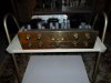
2. The X-1000 operating in the listening room, distinguishing the differences between the stock line amp/control section of Channel A, and the new line amp/control section of Channel B.

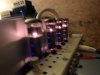
3. The output tubes all lit up and singing happily during the listening tests -- a far cry from the distress these guys indicated they had undergone when the unit was first received.

With proper operation of the new line amp/control section verified, the next step is to get a handle on the power supply hum issue, and then install the new line amp/control section circuits in Channel A. Once those tasks are completed, then, I can tackle the response issues in the power amplifiers.

I'll report back what I find.

Dave
 

Attachments

  • X-1000 Progress 001.jpg
    X-1000 Progress 001.jpg
    97.5 KB · Views: 54
  • X-1000 Progress 002.jpg
    X-1000 Progress 002.jpg
    51.9 KB · Views: 54
  • X-1000 Progress 003.jpg
    X-1000 Progress 003.jpg
    44.3 KB · Views: 52
That unit is certainly a tangled web of issues.
You've been unravelling them wonderfully.
I find this concept of modifying one channel and then doing a comparison very useful.

The basic hum . . . I think that unit has never been completely silent. It will be interesting to see what you come up with there.
 
Hummmmmmm.........

Well, the vast majority of hum was found to be due to a combination of issues -- both from the original design table, and after the unit was built.

As for the after build issue, the replacement components used for the rebuilt low voltage DC power supply that powers the heaters of the small signal tubes was located quite closely to the tone control amplifier stages in both channels -- which are sensitive enough to pick up the EMF radiating from the (relatively) high current involved with the supply's components. Since the tone control amplifier stages appear AFTER the volume control in the X-1000 design, any hum they picked up was sent full strength right on to the speakers.

But by far however, the lions share of the hum is due to the way noise figures are determined. It is common to express them as a figure (in dbs) that is BELOW the rated output of the amplifier. Therefore, a 100 watt amplifier could actually have a lower noise rating than a 10 watt amplifier, but produce more actual noise under quiescent conditions, because there is such a greater power output level for the noise floor to be under. It follows then that for the 100 watt amplifier to have the same actual noise level as a 10 watt amplifier, it must have a much lower noise level than the 10 watt amplifier because the power output is so much greater with the 100 watt unit.

This makes perfect sense, since amplifiers of higher powers would almost certainly be used either with many speakers, less sensitive speakers, or in high ambient noise conditions -- all which work to mask the quiescent noise of the amplifier. And after all anyhow -- what idiot is going to match up a 100 watt amplifier with 101 db efficient speakers in a quiet home environment listening room.....Huh? Well, I guess I'm the idiot........ But with today's more demanding and wider dynamic range source material, and the rather efficient speakers that tube enthusiasts tend to use, it is an issue that definitely deserves attention in view of the other improvements being implemented.

In any event, this meant that the X-1000 in stock form could get by with marginal output stage filtering, and it is certainly marginal to say the least. Do to how much is already crammed into this chassis, there is not a lot of options to correct this -- especially since this whole project is being attempted without a single physical modification to the chassis. That way, if someone is so inclined, the original circuit can be reinstalled........

In any event, there is an option that can help considerably, but will require basically rewiring the HV section of the unit to allow room for its installation -- and just at a time when I thought I could break out and make some real running progress on all the existing modifications already in play.

With this latest effort then, it is now definitely much easier to identify what circuits in the unit either have not or will not change, than to identify those that have. At this point, that would basically be the phono preamp section. Other than that, virtually every other circuit in the unit will undergo some change or modification to implement the improvements discussed, effecting nearly a complete re-engineering of the design.

Geez Louise -- I surely hope I didn't just jinx myself with the phono section.........

Dave
 
I know I rebuilt the bias power supply section, but I put those components where the previous components were. As far as the filament part of the power supply, I don't recall even where that is under the chassis.

As you move forward, you're helping me see why building big power integrateds and receivers has a number of challenges. No wonder there aren't a lot of them.

The phono section has the phono mod in it. It consists of new RIAA components for the phono sections of the PEC from pin 1 to pin 3 on each PEC . . . fyi.

If the chassis must be modified . . . let's talk.
 
Don -- The Low Voltage DC supply for the small signal tube heaters is located immediately behind the tone control amplifier tube on the extreme side of the chassis opposite the end where the phono preamps are located. This tube handles the tone amplification responsibilities for both channels, so any noise this tube might pick up will generally appear in both channels.

In the original build, the caps for this supply were located in the can that resides in the location given, which kept any radiation of the ripple noise from those caps contained within the can. At some point along the journey this amplifier has taken, the can was disabled (but left in place for show), and two new caps installed immediately below the original cap, along with the large dropping resistor, all soldered together in "air connection" style. With these components all hanging out (literally) so close to the tone amplifier stage, it allowed radiated ripple noise from these power supply components to be picked up by the tone amplifiers. This installation can best be seen in the second pic of post #57.

Dave
 
I don't honestly remember redoing a can cap with separate caps in this amp. It's tight in there as it is. I usually suck it up financially and replace the can itself for precisely the reason you state . . . sometimes cans are used for a reason. Space in that amp is a challenge also.

But the chance is that I did something.
Every cook has added salt to the broth.
 
Every cook has added salt to the broth.

No MORE SALT PLEASE! My Blood Pressure is too high for the current standards (which are now low enough, it's a wonder why more people don't pass out when standing up!):D:D
 
Don -- I've never tried to determine who did what, or assign certain work to anyone. This unit has clearly been on a bench a good bit of its life. It almost makes me wonder how much time it has actually spent making music!

Larry -- The CDC has finally come out and said what I felt all along: Salt is not nearly the enemy to good health that it had previously been thought to be. In fact, they are now working to assign/revise MINIMUM daily intake levels! Who would have thought......

Dave
 
I'm simply trying to enhance my skills and assign all blame for workmanship Dave is reworking to myself.

It's one thing to make a mess, it's another thing to make a mess again "after" you should know better. I'm trying to get to that "after" spot.
 
Last edited:
Power Supply Upgrades

With a total reworking of the power supply area, the hum has been dramatically reduced. Most of it was 120 Hz in nature, and seeping in at the power output screen grid and phase inverter stages, since they operate from the least filtered B+ of the power supply. Without much room for even a sneeze in this unit, the idea of including a choke to really go after the problem was out of the question. But with a reworking of the complete power supply area, enough room was created to install a primary filter section before the plate supply to the output tubes. The inclusion of this new filter section means that now the output tube screen grids and phase inverters are filtered by two and three section filters respectively (versus one and two sections respectively in the original design), producing a dramatic reduction in hum: With the inputs to the power amplifier sections shorted, there is virtually no hum or noise from the Cornwalls at all now, versus hum you could quite easily hear within 6-8 feet of the speakers under the same conditions with the stock power supply.

With the tone control amplifiers appearing after the volume control (but before the preamplifier output jacks), and located very closely to the power transformer, there is still some noise these stages produce -- although even that has been significantly reduced with the small signal tube DC heater supply that's located right next door being reinstalled in a more organized fashion. So, the tone control amplifiers will be looked at to see if anything further can be done to reduce the influence they receive from the power supply section that is so close by -- but as is, the hum and noise is now very acceptable, and particularly so when the power output capability of the unit is considered. Altogether, this was a very worthwhile off road excursion, given the overall performance upgrades being sought from the unit.

Pics include:

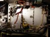
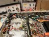
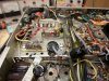
1. In the process of tearing out the bias supply filter caps and low voltage DC heater supply. The old location/installation of the DC heater supply caps can still be seen at the left, while work is also underway on the top deck tearing out (again) the inrush current limiter, and HV B+ supply components. The bias supply diode has now been relocated to the power supply section, from its old location above the tone control amplifiers

2. To make the necessary room for the new filter section components, even small details like reversing the two large 6.3 VAC leads from the power transformer will be necessary -- which hasn't been done yet in this pic.

3. A top shot with the HV section all cleared out, and showing just how little room there is to work with.

4. The reinstallation of the DC heater supply caps and proper mounting of that supply's diode rectifiers on tag boards. The bias supply filter caps have also been relocated from the upper deck to the lower deck now to free up needed room as well. The old DC heater supply filter cap can be plainly seen below, that was previously covered up when the new filter caps were previously laid in, in a horizontal fashion over the old cap. All the is missing from the DC heater supply in this shot is the large dropping resistor.

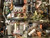
5. The finished rebuild of the entire power supply area. From left, the power cord area had been previously completely reworked, but now the current limiter has been relocated back over closer to the AC power cord area. Continuing to the right, one of two series connected 400 uF/330 volt caps is mounted, that makes up the cap leg of the new primary filter section. Next to that, the tag board where the old HV diodes are now located. Next, the dropping resistor of the new primary filter, and finally, the other 400 uF cap. On the lower deck, the bias filter caps can be seen, as well as the finished DC heater supply components. At the bottom of the pic is the bias diode installation. In the middle right is some wound up wire, which is over the original second stage line amp of Channel A. The wiring represents necessary connections for that channel to still work as originally designed, but with half of the support wiring for it removed. Finally, in the bottom right, the tone control amplifiers can be seen, which have also been cleaned up to help reduce hum and noise. Directly above that section, is the new Channel B line stage amplifier previously installed.

A bit of a break for now, and then back to finishing installation of the Channel B control circuits (the tone control bypass switch), and then it will be on to the power amps. Once Channel B is fully complete, then more listening tests, and performance documentation will be done between the two channels. After that, work will start -- from the beginning -- on the installation of a new Channel A.


Dave
 

Attachments

  • 2013_0727group10007.jpg
    2013_0727group10007.jpg
    156.5 KB · Views: 46
  • 2013_0727group10006.jpg
    2013_0727group10006.jpg
    117.9 KB · Views: 45
  • 2013_0727group10003.jpg
    2013_0727group10003.jpg
    87.2 KB · Views: 44
  • 2013_0727group10004.jpg
    2013_0727group10004.jpg
    116 KB · Views: 47
  • 2013_0727group10005.jpg
    2013_0727group10005.jpg
    97.1 KB · Views: 48
It's interesting how something as simple as reorienting those 1500uf bias supply caps makes a difference and opens up some space.

Here are two photos.
One is the original stock X-1000 (later front panel and schematic style) that I received from Buglegirl and sold.

attachment.php


The second one is the unit Dave is working on from before I sent it to him.

The second one is a link to a photo AK already has on this from the thread "Is this motorboating and how do I control it.
http://www.audiokarma.org/forums/attachment.php?attachmentid=390309&d=1353207561

I believe the can cap that is unused now was now for the low voltage filament supply, but instead contained the two negative bias power supply caps now replaced by the two 1500uf nichicons in Dave's photos.
 

Attachments

  • frontpanel1204_underchassis.jpg
    frontpanel1204_underchassis.jpg
    130.4 KB · Views: 156
Last edited:
Don -- I'm investigating the possibility that there may be a ground loop associated with the tone control amplifier stages, causing the residual noise left in the unit. But even if no further improvement can be made in the tone control section, there should still be some improvement to be had, as ultimately, the tone controls (and the tone control amplifiers) will be made optional -- to be switched into the circuit as desired, since the normal state of operation will otherwise have them removed (bypassed) from the signal path.

It is not surprising that both of these units have suffered significant output tube arc events. The operating conditions in the X-1000 are a textbook example of the factors that can come together to cause such events, that I wrote of many years ago (in AudioXpress), in what is still the only article addressing such issues, and where I first proposed screen stability resistors as a solution to address the problem. It is a solution that has been validated countless numbers of times now for those who have had to pick up the pieces from such damage.

Finally, the two (originally) 1000 uF caps (located in the now unused can) were in fact the filter caps for the small signal tubes DC heater supply, while the bias filter caps are the three smaller electrolytic caps located on and just off of the upper deck over the bias controls.

In any event, having some pics of what represents (as closely as possible) the original build helps to know what the original intentions of Fisher engineers were in building these beasts!

Dave
 
Last edited:
Another Detour

Testing has revealed that the area on the lower deck in front of the total width of the power transformer on the X-1000 chassis is contaminated for audio grounding purposes. It's fine for power supply grounding relative to the bias and DC heater supply circuits. But any active amplification stages grounded in this area will pick the ground noise, and send it on with the signal -- which is exactly what was happening with the tone control amplifiers located there. The new Channel B line stage amplifier is located on the inside edge of this area as well -- but since it appears before the volume control in the design, the noise it picks up can only be heard at elevated volume settings. Noise from these circuits couldn't be heard before, for all of the hum from the insufficient power supply filtering -- and because the individual gain stages of the new line stage amplifier have less amplification to them (for reasons previously discussed), making them less susceptible to hum pickup as well. With the power supply filter issue resolved however, the issue with these circuits was then made apparent.

Any amplifier striving for the highest possible fidelity reproduction should have the lowest possible noise content, as any such noise works to mask low level detail in the sonic presentation. So work on hum reduction in the X-1000 continues on.

Further testing and a review of the possible fixes determined that removing all audio ground connections in this area -- mine, and those from the original build as well -- and installing a new ground buss system to support the audio grounds for the area would be the best way to go.

Providing a good grounding system is essential to proper operation of the final product, as it is the support system on which all the active circuits rests. So, another detour will be made to get the final bugs out of the hum issues with this amplifier, before proceeding with the rest of the modification process.

Dave
 
Isolated Ground Buss

Sometimes, individual parts of a modification effort seem to produce little in return by themselves for the effort it took to implement them. But other times, it's those very efforts that unlock the door for returns on a chain of efforts to come flooding in. So it is with the initially obscene hum levels this unit produced at first start up. Initially, it was found that the tone control amplifier stages were connected to the wrong B+ supply point, supplying less filtered B+ to these stages. But correcting this produced only small reductions in hum. Then the lack of adequate filtering for the output stage B+ was documented and corrected. This returned big gains in hum reduction, producing generally acceptable results for a unit of this power level. But it still didn't let the unit operate as quietly as a unit of this caliber should. Then the dirty audio grounds were identified and eliminated for the audio circuits in close proximity to the power supply area, and a new isolated ground circuit was installed to support these circuits. And that unlocked the door.

The X-1000 is now extremely quiet, requiring you to place your ear literally right up against the speaker board of my 101 db Cornwalls to hear any noise at all. The noise floor is extremely low for any system now, but impressively so considering that this a 100 watt system -- and an integrated 100 watt system at that. In short, the unit now acts like a Fisher of this caliber level should: Quiet, powerful, and smooth -- just doing what it does so well.

For any other X-1000 owners following along, there have been three basic parts of this modification effort that have been identified as really a must for any X-1000 amplifier:

1. Install screen stability resistors in the output stage to all but eliminate any tendency towards output tube arcing.

2. Install a new filter section immediately coming off the bridge rectifier before the output stage to significantly lower hum in the output. This modification will also lower distortion levels as well by reducing the power supply's modulating effects on the output stage at high power levels.

3. Provide a new, clean, isolated ground for the audio circuits in the vicinity of the power supply area.

These three efforts will take your output tubes out of harms way from a design standpoint, and dramatically reduce the hum levels of this amplifier as originally designed as well. I'll be happy to provide details to anyone so wishing to install them.

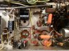
The single pic provided shows the tone control amplifiers and new Channel B line stage amplifier with the new ground buss circuit installed. At the line amplifier, all the connections originally made to a ground tag have now been moved over to an unused isolated tag on the same T-strip, while over in the tone control amplifier area, the components requiring grounding now all stand up vertically, with their ground leads all routed over to a new isolated T-strip mounted on the right side of the chassis, where the old selenium bias supply rectifier was originally mounted. These two new isolated ground points have been connected together, and ultimately, are then grounded to the chassis over in the area behind the balance control. And with that, the hum is now gone.

With the hum problem finally nailed down, now I can finally take a bit of a break to get some other projects caught back up, but will return back to the X-1000 in a few days to get it back on track with the original laundry list of modifications to be installed.

Dave
 

Attachments

  • X-1000 Isolated Ground Buss 003.jpg
    X-1000 Isolated Ground Buss 003.jpg
    131.9 KB · Views: 54
Back
Top Bottom