

You are using an out of date browser. It may not display this or other websites correctly.
You should upgrade or use an alternative browser.
You should upgrade or use an alternative browser.
Fisher X-1000 integrated - Welcome
- Thread starter audiodon
- Start date


At one point in my efforts to reduce the hum, I contacted Don to learn how the output stage high current grounds were originally effected by Fisher, and even tried routing all the output tube cathode grounds directly back to the negative supply point of the B+ bridge rectifier through a separate lead to keep these currents out of the chassis. I also checked the resistance of each mechanical ground point made to the chassis, which were found to be intact with high integrity. None of these efforts proved to provide any improvement.
As a side note, I am sure this is why Fisher gave up on the high copper content chassis they used throughout the 50's, as nearly every ground in the SA-100 I installed EFB into (which used this kind of chassis) was compromised. On the other hand, none were compromised in the more modern chassis of the X-1000.
Ultimately, in the X-1000, the final bit of hum was simply due to the EMF of the power transformer radiating out some distance into the chassis, for any nearby amplifier stages to pick up and inject into the signal path. This was not a ground loop problem per se, as the tone control amplifier stages had all their grounds made to basically the same point in the area, and are also very low current grounds at that -- on the order of only a couple of ma or so of current draw. Simply grounding all of the components in these circuits requiring a ground connection further away from the power transformer area did the trick.
Dave
As a side note, I am sure this is why Fisher gave up on the high copper content chassis they used throughout the 50's, as nearly every ground in the SA-100 I installed EFB into (which used this kind of chassis) was compromised. On the other hand, none were compromised in the more modern chassis of the X-1000.
Ultimately, in the X-1000, the final bit of hum was simply due to the EMF of the power transformer radiating out some distance into the chassis, for any nearby amplifier stages to pick up and inject into the signal path. This was not a ground loop problem per se, as the tone control amplifier stages had all their grounds made to basically the same point in the area, and are also very low current grounds at that -- on the order of only a couple of ma or so of current draw. Simply grounding all of the components in these circuits requiring a ground connection further away from the power transformer area did the trick.
Dave
OK. What was supposed to be just a few days off ended up being nearly two weeks of non stop life on the go, which included finishing up a couple of beautiful Fisher 50C preamplifiers for a client, finishing the development of EFB parameters for the bazillions of 30-35 watt/channel amplifier/receivers out there using the 7591 family of tubes, and spending time with a brand new grandson. So now, with the 50Cs packaged up and ready for shipment, the EFB data all determined, and the grandson only awake once during the night now, it's back to the X-1000.
The only thing that had not been finished in the Channel B control section when I left off is the addition of the tone control on/off switch, which should be relatively easy to execute. That leaves the next big area to tackle in the design then, which is the power amplifier circuits.
In stock form, these have the oh so typical Fisher roll off in frequency response that can really act to lose transient detail information. That, and the fact that the common output terminals are not at ground level in this unit. In the real world, this prevents using the unit with any type of common ground speaker switching systems, and in the lab on the test bench, it can cause all manner of shorts between test equipment that has common grounds through three wire AC plugs, or otherwise. In short, these designs are a pain in the butt. So, as one more modification in this exercise, this design detail (done to allow a powered center channel speaker to be used) will be removed. Good riddance.
To correct the former problem will require a thorough reworking of the HF stability control circuits,since it has already been previously determined that excellent HF response AND HF stability can both be had in the power amplifier section. Correcting the latter problem will be achieved by reversing the phase of the output transformers so that the common output terminals can be grounded, and still have the NFB signal (now to be taken from the 4 ohm tap) still in fact be negative.
Once this is done, then again, a modified channel B to stock Channel A sonic comparison can be done to keep a weather eye on where this is all going. After that, the tone control switch can be added, and final completely modified Channel B comparison can be made to the completely stock Channel A.
More to follow soon!
Dave
The only thing that had not been finished in the Channel B control section when I left off is the addition of the tone control on/off switch, which should be relatively easy to execute. That leaves the next big area to tackle in the design then, which is the power amplifier circuits.
In stock form, these have the oh so typical Fisher roll off in frequency response that can really act to lose transient detail information. That, and the fact that the common output terminals are not at ground level in this unit. In the real world, this prevents using the unit with any type of common ground speaker switching systems, and in the lab on the test bench, it can cause all manner of shorts between test equipment that has common grounds through three wire AC plugs, or otherwise. In short, these designs are a pain in the butt. So, as one more modification in this exercise, this design detail (done to allow a powered center channel speaker to be used) will be removed. Good riddance.
To correct the former problem will require a thorough reworking of the HF stability control circuits,since it has already been previously determined that excellent HF response AND HF stability can both be had in the power amplifier section. Correcting the latter problem will be achieved by reversing the phase of the output transformers so that the common output terminals can be grounded, and still have the NFB signal (now to be taken from the 4 ohm tap) still in fact be negative.
Once this is done, then again, a modified channel B to stock Channel A sonic comparison can be done to keep a weather eye on where this is all going. After that, the tone control switch can be added, and final completely modified Channel B comparison can be made to the completely stock Channel A.
More to follow soon!
Dave

Power Amplifiers: The LF End
The design of the power amplifiers in the X-1000 is more complex than the usual Fisher offerings. They are essentially a Dynaco MK II in topology, except that the output stage is not UL, and equally important, the coupling between the EF86 pentode input stage and 1/2 12AU7 cathodyne phase inverter includes a traditional coupling cap -- as opposed to the direct coupling used at this point in the Dynaco. Both of these elements have a significant impact on the design of the X-1000's power amplifiers.
With precious few exceptions, Fisher gear almost always uses pentode output stages. This eliminated any potential patent concerns if UL were used, and simplified OPT design as well. But because of the inherently high output impedance that pentode operation produces, pentode designs always require a significant amount of NFB to achieve the characteristics required of a good audio amplifier. But applying high levels of feedback can add complications back into the design if good stability is also to be achieved. The power amplifiers in the X-1000 use about the same amount of NFB as say that used in their 400, 500, and 800 receivers (~20 db). But when big output transformers are involved in a design that employes this much NFB, and which also includes multiple capacitively coupled stages, the complications grow exponentially. The power amplifiers in the X-1000 contain all of these things.
The coupling cap between the EF86 and 1/2 12AU7 was included to eliminate the oh so typical concerns that often occur when direct coupling is used from a pentode stage: Unless the pentode is carefully selected, variations in it's operating point can produce wild shifts in the operating point of the phase inverter stage it is directly coupled to -- which can produce wild shifts in delivered performance. Including a coupling cap eliminates these concerns by separating the two stages with regards to their static DC characteristics. This was a great move that Fisher did to maintain their reputation of non-fussy operation: The design is largely insensitive to the individual tubes used in the power amplifier driver section.
But the coupling cap also introduces an additional pole with it's attendant phase shift within the feedback loop, which can upset LF stability. To address this, Fisher really did their homework by including phase shifting networks of opposite characteristics in each leg of the phase inverter feeding the output tubes. As a result, the LF stability of these amplifiers is near perfect: DC transients settle virtually instantly, with the subsonic frequency response tailoring off in a very smooth and controlled fashion -- meeting the published spec quite handily (-2 db @ 5 Hz). With performance such as this, there is plenty of reason to leave well enough alone with regards to the LF stability elements of the stock design. The performance is superb, leaving nothing to want. The HF end of the spectrum is another story however. There, opportunity is ripe, and is coming up shortly.
Dave
The design of the power amplifiers in the X-1000 is more complex than the usual Fisher offerings. They are essentially a Dynaco MK II in topology, except that the output stage is not UL, and equally important, the coupling between the EF86 pentode input stage and 1/2 12AU7 cathodyne phase inverter includes a traditional coupling cap -- as opposed to the direct coupling used at this point in the Dynaco. Both of these elements have a significant impact on the design of the X-1000's power amplifiers.
With precious few exceptions, Fisher gear almost always uses pentode output stages. This eliminated any potential patent concerns if UL were used, and simplified OPT design as well. But because of the inherently high output impedance that pentode operation produces, pentode designs always require a significant amount of NFB to achieve the characteristics required of a good audio amplifier. But applying high levels of feedback can add complications back into the design if good stability is also to be achieved. The power amplifiers in the X-1000 use about the same amount of NFB as say that used in their 400, 500, and 800 receivers (~20 db). But when big output transformers are involved in a design that employes this much NFB, and which also includes multiple capacitively coupled stages, the complications grow exponentially. The power amplifiers in the X-1000 contain all of these things.
The coupling cap between the EF86 and 1/2 12AU7 was included to eliminate the oh so typical concerns that often occur when direct coupling is used from a pentode stage: Unless the pentode is carefully selected, variations in it's operating point can produce wild shifts in the operating point of the phase inverter stage it is directly coupled to -- which can produce wild shifts in delivered performance. Including a coupling cap eliminates these concerns by separating the two stages with regards to their static DC characteristics. This was a great move that Fisher did to maintain their reputation of non-fussy operation: The design is largely insensitive to the individual tubes used in the power amplifier driver section.
But the coupling cap also introduces an additional pole with it's attendant phase shift within the feedback loop, which can upset LF stability. To address this, Fisher really did their homework by including phase shifting networks of opposite characteristics in each leg of the phase inverter feeding the output tubes. As a result, the LF stability of these amplifiers is near perfect: DC transients settle virtually instantly, with the subsonic frequency response tailoring off in a very smooth and controlled fashion -- meeting the published spec quite handily (-2 db @ 5 Hz). With performance such as this, there is plenty of reason to leave well enough alone with regards to the LF stability elements of the stock design. The performance is superb, leaving nothing to want. The HF end of the spectrum is another story however. There, opportunity is ripe, and is coming up shortly.
Dave
Last edited:

audiodon
Addicted Member
In some ways, it appears that the X-1000 was a transitional design for Fisher's development engineers, with transitions built into the X-1000 from the previous generation, and then further changes for subsequent designs based on the learning experience and expense of implementation of designs new to the X-1000.
For this new (at the time) design, Fisher abandoned the copperized chassis of the SA-300B amplifier and settled on the cadmium plated steel chassis used in the TA-500 and TA-600 receivers. The SA-300's design used an ECC82 (12AU7) phase inverter.
Electronically, the X-1000 has a unique (for Fisher anyway) phase inverter circuit including the EF-86 and half a 12AU7.
Fisher also abandoned the brass faceplate and knob style during the X-1000's production run.
How much of the X-1000's circuit was put in place to adequately drive the center channel I'm not sure.
The X-202-B, the X-1000's smaller cosmetically similar sibling that used the (at that time) new 7591 output tube used 7247s inputting to 12AX7 phase inverters.
Later designs all used 12AX7 tubes for phase inverters.
For this new (at the time) design, Fisher abandoned the copperized chassis of the SA-300B amplifier and settled on the cadmium plated steel chassis used in the TA-500 and TA-600 receivers. The SA-300's design used an ECC82 (12AU7) phase inverter.
Electronically, the X-1000 has a unique (for Fisher anyway) phase inverter circuit including the EF-86 and half a 12AU7.
Fisher also abandoned the brass faceplate and knob style during the X-1000's production run.
How much of the X-1000's circuit was put in place to adequately drive the center channel I'm not sure.
The X-202-B, the X-1000's smaller cosmetically similar sibling that used the (at that time) new 7591 output tube used 7247s inputting to 12AX7 phase inverters.
Later designs all used 12AX7 tubes for phase inverters.
Don -- The only consideration for driving a center channel speaker is available power -- which in turn means the output stage -- and what ever driver needs it has -- is the only real consideration when a center channel speaker connection is made available. In my experience, these were primarily available on the 30-35 watt/channel receiver amplifiers, so at 50 watts per, the X-1000 has more than enough power available. Heck, even the Dynaco SCA-35 has provisions for driving a center channel speaker.
The reason for using an EF86 is because in this design, EL34 output tubes require basically double the amount of driving voltage that 7591 class tubes do. If the input voltage requirement of the power amplifier section is to remain similar to other "blocks" of Fisher power amplifier designs (this to allow interchangeability with the basic Fisher phono preamp and control section blocks), that means that the AF amplifier stage must have twice the gain versus that which the stage would be required to have were 7591 tubes to be used. In fact, with EL34 tubes, 20 db of NFB, and an input sensitivity of 2.0 vac (for the power amplifier section), the AF amplifier stage in the power amplifiers of the X-1000 must have a gain of about 140, which is well beyond what a 12AX7 gain stage can provide. Therefore, the EF86 pentode was used in the AF amplifier stage, and 1/2 of a 12AU7 was used for the phase inverter.
Dave
The reason for using an EF86 is because in this design, EL34 output tubes require basically double the amount of driving voltage that 7591 class tubes do. If the input voltage requirement of the power amplifier section is to remain similar to other "blocks" of Fisher power amplifier designs (this to allow interchangeability with the basic Fisher phono preamp and control section blocks), that means that the AF amplifier stage must have twice the gain versus that which the stage would be required to have were 7591 tubes to be used. In fact, with EL34 tubes, 20 db of NFB, and an input sensitivity of 2.0 vac (for the power amplifier section), the AF amplifier stage in the power amplifiers of the X-1000 must have a gain of about 140, which is well beyond what a 12AX7 gain stage can provide. Therefore, the EF86 pentode was used in the AF amplifier stage, and 1/2 of a 12AU7 was used for the phase inverter.
Dave
Power Amplifiers: The HF End
After all the hassles Fisher went through with the stability concerns of the boxcar amplifiers, they really went overboard ensuring good HF stability with the X-1000. The stated frequency response of the power amplifier section alone is to 50 kHz, within -2 db -- a specification this unit had no prayer of meeting. This was evident by the very rounded leading edge on a 10 kHz square wave presentation shown in an earlier post. In fact, the BEST channel of this unit measured as follows:
1 kHz = 0 db (ref)
10 kHz = -.25 db
20 kHz = -1.0 db
25 kHz = -1.2 db
30 kHz = -1.4 db
40 kHz = -2.45 db
50 kHz = -3.25 db
Initial tests showed that the output transformers have an extended frequency response well above this range. But big output transformers also typically have notably more ringing to them as well as feedback is increased -- and these do ring.
UL OPTs have an inherent advantage in this regard, since the UL feedback connection tends to dampen the ringing, requiring less circuit remedies to control it. But, that's not the case at hand, so we deal with what we've got, which is a big, non UL transformer, with good frequency response, but with some serious ring as well. Controlling the ring will necessarily limit the stable frequency response that can ultimately be achieved, with Fisher's specification likely being a best case scenario. With the poor showing of displayed/measured performance versus that specified, the hunt was on to see if it could be improved.
Fisher used no less than four different stability networks in the power amplifiers of the X-1000 to get a handle on the ringing and HF stability. These include:
1. A traditional phase advance cap across the feedback resistor.
2. Feedback from the plate of the bottom output tube.
3. A kick cap at the output from the plate side of the phase inverter.
4. A traditional step network from the plate of the EF86 stage to ground.
These all work to produce excellent stability, but at a notable expense to transient response. To see just what could be done in the way of improvement, it was all removed to start fresh and see where that might lead.
As a side note, some attention has been given in recent threads as to just what a proper 10 kHz square wave should look like on the output of a power amplifier. The answer is, that depends on the load -- with some of the loudest voices missing that fact.
Examining a square wave across a non-inductive load resistor is one thing -- but that is no guarantee of how the amplifier will respond to more typical loads that a speaker might present, which can range anywhere from almost no load, to a capacitive only load, to an inductive load, to a purely resistive load. Normally, a speaker will represent some element of all these characteristics at once (which makes up the term: impedance), with no load and a capacitive only loads presenting the biggest problems for the amplifier.
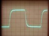
The pics show the results of the various approaches used in this effort. The first pic is a 10 kHz square wave, as produced by the stock design of the Fisher x-1000 power amplifiers, operating into a purely resistive load.
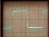
A first effort towards improvement was made (using the same basic feedback level in all instances), employing just a traditional feedback cap, and step network. This produced a good frequency response (within 1 db to nearly 60 kHz), and even a decent square wave -- as shown in the second pic. However, when a cap only load was applied, look what happened in the third pic. Even though the square wave produced across a purely resistive load was very nice, this represents a very unstable feedback amplifier on a speaker load, and shows why square waves must be examined under a variety of loads to ensure that complete stability has been achieved. In this case, the wave form is never damped out, with ringing extending fully to the end of the wave top.
The output transformers were tested and found to contain two resonate peaks, which explains why the small feedback cap was used from the plate of the bottom output tube. The traditional feedback cap acts primarily on the first peak, while the plate feedback cap acts on the second. The effect of the kick cap (which actually acts to increase frequency response, hence the name) is small, but acts to promote a smooth transition between the two feedback networks. Ultimately, it was found that the stock values chosen for the traditional feedback cap, plate feedback cap, and kick cap were all very appropriate for the circuit. But then there was the step network at the plate of the EF86.
This network was found to have a very heavy hand, reducing circuit response to well below that required to achieve good HF stability. The result is a needless intrusion into the response of the upper regions of the audio bandwidth. In working with that network then, even the capacitive element was found to be well suited for the design. It was the resistive element that was doing all the damage.
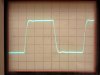
This resistor was originally a 22k resistor, but a value 1/10 that amount was found to be much more suitable for the design. Substituting in a 2.2K resistor in this network produced a frequency response of +0/-.2 db to 20 kHz, and +0/-1 db to 40 kHz. Even the original Fisher specification was met, with response at 50 kHz being down 1.8 db. The resulting square wave shows the worthwhile improvement achieved over that of the original design.
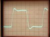
The fourth pic shows the finished result into a purely resistive load, while the fifth pic show the effect of a 1 uF cap added across the output. With a 1 uF cap only load, the effect in pic #5 is somewhat more pronounced, but substantially the same. As you can see then, even though pic #2 and #4 are very similar and imply a very smooth HF response, only by also showing the loading condition of pic #5 do you really know that the design depicted in pic #4 is also quite stable under the most adverse load conditions.
With the power amplifier HF response resolved, I will now go back and install the tone control on-off switch in Channel B, and then be able to compare the complete, fully modified Channel B (from input to output) -- both with, and without tone controls engages -- to an otherwise substantially stock Channel A. Obviously, Channel A has also benefited from the power supply and grounding improvements, as well as the addition of screen stability resistors, but is otherwise bone stock. However, these improvements are common to both channels, so the differences noted then will be due solely to the redesign of the various audio circuits in Channel B, versus their counterparts in the stock circuits in Channel A.
A couple days off to visit my dad, but should be able to report my observations of this test later this weekend.
Dave
After all the hassles Fisher went through with the stability concerns of the boxcar amplifiers, they really went overboard ensuring good HF stability with the X-1000. The stated frequency response of the power amplifier section alone is to 50 kHz, within -2 db -- a specification this unit had no prayer of meeting. This was evident by the very rounded leading edge on a 10 kHz square wave presentation shown in an earlier post. In fact, the BEST channel of this unit measured as follows:
1 kHz = 0 db (ref)
10 kHz = -.25 db
20 kHz = -1.0 db
25 kHz = -1.2 db
30 kHz = -1.4 db
40 kHz = -2.45 db
50 kHz = -3.25 db
Initial tests showed that the output transformers have an extended frequency response well above this range. But big output transformers also typically have notably more ringing to them as well as feedback is increased -- and these do ring.
UL OPTs have an inherent advantage in this regard, since the UL feedback connection tends to dampen the ringing, requiring less circuit remedies to control it. But, that's not the case at hand, so we deal with what we've got, which is a big, non UL transformer, with good frequency response, but with some serious ring as well. Controlling the ring will necessarily limit the stable frequency response that can ultimately be achieved, with Fisher's specification likely being a best case scenario. With the poor showing of displayed/measured performance versus that specified, the hunt was on to see if it could be improved.
Fisher used no less than four different stability networks in the power amplifiers of the X-1000 to get a handle on the ringing and HF stability. These include:
1. A traditional phase advance cap across the feedback resistor.
2. Feedback from the plate of the bottom output tube.
3. A kick cap at the output from the plate side of the phase inverter.
4. A traditional step network from the plate of the EF86 stage to ground.
These all work to produce excellent stability, but at a notable expense to transient response. To see just what could be done in the way of improvement, it was all removed to start fresh and see where that might lead.
As a side note, some attention has been given in recent threads as to just what a proper 10 kHz square wave should look like on the output of a power amplifier. The answer is, that depends on the load -- with some of the loudest voices missing that fact.
Examining a square wave across a non-inductive load resistor is one thing -- but that is no guarantee of how the amplifier will respond to more typical loads that a speaker might present, which can range anywhere from almost no load, to a capacitive only load, to an inductive load, to a purely resistive load. Normally, a speaker will represent some element of all these characteristics at once (which makes up the term: impedance), with no load and a capacitive only loads presenting the biggest problems for the amplifier.
The pics show the results of the various approaches used in this effort. The first pic is a 10 kHz square wave, as produced by the stock design of the Fisher x-1000 power amplifiers, operating into a purely resistive load.
A first effort towards improvement was made (using the same basic feedback level in all instances), employing just a traditional feedback cap, and step network. This produced a good frequency response (within 1 db to nearly 60 kHz), and even a decent square wave -- as shown in the second pic. However, when a cap only load was applied, look what happened in the third pic. Even though the square wave produced across a purely resistive load was very nice, this represents a very unstable feedback amplifier on a speaker load, and shows why square waves must be examined under a variety of loads to ensure that complete stability has been achieved. In this case, the wave form is never damped out, with ringing extending fully to the end of the wave top.
The output transformers were tested and found to contain two resonate peaks, which explains why the small feedback cap was used from the plate of the bottom output tube. The traditional feedback cap acts primarily on the first peak, while the plate feedback cap acts on the second. The effect of the kick cap (which actually acts to increase frequency response, hence the name) is small, but acts to promote a smooth transition between the two feedback networks. Ultimately, it was found that the stock values chosen for the traditional feedback cap, plate feedback cap, and kick cap were all very appropriate for the circuit. But then there was the step network at the plate of the EF86.
This network was found to have a very heavy hand, reducing circuit response to well below that required to achieve good HF stability. The result is a needless intrusion into the response of the upper regions of the audio bandwidth. In working with that network then, even the capacitive element was found to be well suited for the design. It was the resistive element that was doing all the damage.
This resistor was originally a 22k resistor, but a value 1/10 that amount was found to be much more suitable for the design. Substituting in a 2.2K resistor in this network produced a frequency response of +0/-.2 db to 20 kHz, and +0/-1 db to 40 kHz. Even the original Fisher specification was met, with response at 50 kHz being down 1.8 db. The resulting square wave shows the worthwhile improvement achieved over that of the original design.
The fourth pic shows the finished result into a purely resistive load, while the fifth pic show the effect of a 1 uF cap added across the output. With a 1 uF cap only load, the effect in pic #5 is somewhat more pronounced, but substantially the same. As you can see then, even though pic #2 and #4 are very similar and imply a very smooth HF response, only by also showing the loading condition of pic #5 do you really know that the design depicted in pic #4 is also quite stable under the most adverse load conditions.
With the power amplifier HF response resolved, I will now go back and install the tone control on-off switch in Channel B, and then be able to compare the complete, fully modified Channel B (from input to output) -- both with, and without tone controls engages -- to an otherwise substantially stock Channel A. Obviously, Channel A has also benefited from the power supply and grounding improvements, as well as the addition of screen stability resistors, but is otherwise bone stock. However, these improvements are common to both channels, so the differences noted then will be due solely to the redesign of the various audio circuits in Channel B, versus their counterparts in the stock circuits in Channel A.
A couple days off to visit my dad, but should be able to report my observations of this test later this weekend.
Dave
Attachments
-
 X-1000 Power Amplifier HF Stability Tests 005.jpg38.7 KB · Views: 11
 -
 X-1000 Power Amplifier HF Stability Tests 001.jpg43.2 KB · Views: 11
 -
 X-1000 Power Amplifier HF Stability Tests 002.jpg47.1 KB · Views: 11
 -
 X-1000 Power Amplifier HF Stability Tests 003.jpg43.8 KB · Views: 13
 -
 X-1000 Power Amplifier HF Stability Tests 004.jpg48.1 KB · Views: 14
audiodon
Addicted Member
Dayum!
The attention to detail Dave is using is truly exceptional and shows the years of experience as well as an intuitive and inquisitive mind.
I've worked in engineering environments as a technical writer for 25+ years and this analysis and description rates right up there with the best I've seen . . . as applied to my favorite pastime.
The attention to detail Dave is using is truly exceptional and shows the years of experience as well as an intuitive and inquisitive mind.
I've worked in engineering environments as a technical writer for 25+ years and this analysis and description rates right up there with the best I've seen . . . as applied to my favorite pastime.

Don; I sure as hell couldn't say it any better.
Larry
Larry
Rounding Third For Home!
All of the modifications discussed have been completely installed into Channel B, such that the wiring for that channel is now complete. For review, those modifications include:
A. Removal of the bleed circuit between the Tape Monitor and Aux 1 inputs.
B. Removal of the active Phase Reversal switch circuitry.
C. Removal of the Center Channel Record Output jack circuitry.
D. Removal of the Reverb Input/Output jack circuitry.
E. Removal of the Remote Volume Control connector circuitry.
F. Removal of the powered center channel output circuitry.
G. Removal of the Low Filter switch circuitry.
H. Removal of the High Filter switch circuitry.
I. Removal of the old three stage line amplifier design.
J. Relocation the Tape Monitor Input switch to immediately after the Mode Switch to equalize the gain of this input with that of the other high level inputs, and to eliminate the phase reversal that existed between the Tape Monitor Input and the other high level inputs.
K. Relocation the Record Output jack signal to be sourced directly from the Mode Switch. This eliminates the phase reversal that existed between the source and record output signals.
L. Providing a low output impedance unity gain buffer to isolate the Record Output jacks from the internal signal path in the amplifier.
M. Install a new two stage design 12AU7 based line stage amplifier, eliminating the need for 7247 tubes, as used in the original design.
N. Convert the old High Filter switch into a Tone Control "ON" switch, to allow the tone controls to be included in the signal path when desired.
O. Convert the old Reverb In/Out jacks into Preamp Output/Power Amp Input jacks.
P. Provide a low output impedance unity gain buffer to drive the new Preamp Output jacks.
Q. Convert the power amplifier section to have the Common output terminals operate at ground level.
R. Correct HF stability circuits in the power amp section to optimize HF response while maintaining excellent stability and distortion characteristics.
S. Install new output stage B+ plate supply filter to eliminate significant 120 Hz hum in output.
T. Provide new low noise ground point for all grounds in the tone control amplifier circuitry to eliminate notable hum in the output.
U. Correct as received issues with broken rear panel leads, exploded output tube cathode resistor, bias supply, tone control stage B+ supply, coupling circuits into the left channel output stage, installation of screen stability resistors, AC wiring, and installation of appropriate current inrush device.
With the conclusion of this litany of changes, I have now been able to get some serious listening time in with the stock Channel A, and the modified Channel B -- both with the tone controls in, and out of the signal path. I list all these changes not to impress, but to give a full understanding of the scope of changes being made. This was also the first time (other than when I first made the necessary repairs) I have been able to listen to the unit with it fully buttoned up after Channel B has been finished.
In this latest listening test, a number of observations were obvious from the get-go, and include:
1. On 101 db efficient speakers, the unit is nearly dead quiet now, requiring your ear to be firmly against the speaker board to hear anything. The horns only emit a very quiet hiss, indicating that amplification is taking place.
2. Advancing the volume to full with no input to the Aux jacks produces a notable increase in hiss from Channel A, while the same conditions produce only a very slight increase in hiss in Channel B. The difference in noise between the two channels is quite significant, particularly considering the power output capability at play here.
3. Placing a dead short on the Record Output jack of channel A kills all sound in that channel. A dead short on the Record Output jack of channel B causes no change in the sonic character of that channel at all.
4. Throughout all of the significant development work, the output tubes have held their bias settings very solidly. With the addition of the screen stability resistors, they seem very stable in operation, and quite happy in their task.
In spite of all these changes, this unit still commands its identity as that of a Fisher X-1000. Outwardly, only the LF & HF filter, and phase reverse switches no longer function (HF filter switch is now the TC ON switch), while the wiring to the unused SpaceXpander control has been removed. On the back panel, the Remote Volume and SpaceXpander connection jacks have been disabled, as have been the powered center channel output and Center Channel Record output jack. All other functions and features of the unit remain in place, and now include the new Pre Out/Power In jacks as well. The active controls all still work very quietly and smoothly in operation as before. Input sensitivity and impedance are also identical to the original specifications.
Sonically, the new channel is very similar in many ways to the old channel, but includes some important differences: The bass is notably deeper in the modified channel, and the highs are smoother, but with more detail. Overall, the presentation is more balanced. On lower quality recordings, the changes are hardly noticeable, while on high quality recordings, the difference is striking. Considering the improved sonic presentation, complete absence of noise, and worthwhile feature changes, I think the re-engineered unit is a much more capable device, while still retaining the best of its original purpose and features.
With this then, all that remains is to document the performance between the two channels, and then start the installation of these modifications into Channel A. Since much of the groundwork to accomplish that has already been performed with the work of installing the modifications into Channel B, it will go much, much quicker from this point, although the original Channel A line stage design must obviously first be removed before installation can begin. Still, this project is rounding third for home.
For now, pics include:
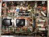
1. This 12AX7 tube will ultimately perform as the Recording Output Jack Buffer stages for both channels. For now, it is serving that function with the wiring on the right side for Channel B, while the original wiring on the left side is the input stage of the Channel A three stage line amplifier in the original design.
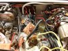
2. This tube is still the second and third stage of the original line stage for Channel A, while the two switches behind it are the Tape Monitor and (new) Tone Control On switches. The right side of each switch represents new Channel B wiring, while the left side of these switches still performs their original functions as designed.
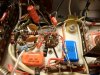
3. A close up of the tone control amplifier. I ran out of available t-strip terminals, so I secured an isolated strip on the back of the Stereo Dimension Control with adhesive to allow for secure connections to be made. These connections represent the output of the tone control amplifier stage. The single black wire over the Dimension Control maintains the original Channel A connection, while the strip ultimately allows for the shielded cable connections to be made, that route this signal over to the TC On switch in the new design.
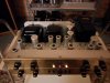
4. A complete view of the bottom side as it currently exists with Channel B completely finished, and Channel A awaiting installation of its modifications.
5. Running quite happily after about 10 hours into the first listening session.
With the end in sight, Don will soon be able to add his critical analysis as to his performance perceptions as well, which I certainly welcome. He will need to get a couple of good 12AU7s ready, as it won't be long now!
Dave
All of the modifications discussed have been completely installed into Channel B, such that the wiring for that channel is now complete. For review, those modifications include:
A. Removal of the bleed circuit between the Tape Monitor and Aux 1 inputs.
B. Removal of the active Phase Reversal switch circuitry.
C. Removal of the Center Channel Record Output jack circuitry.
D. Removal of the Reverb Input/Output jack circuitry.
E. Removal of the Remote Volume Control connector circuitry.
F. Removal of the powered center channel output circuitry.
G. Removal of the Low Filter switch circuitry.
H. Removal of the High Filter switch circuitry.
I. Removal of the old three stage line amplifier design.
J. Relocation the Tape Monitor Input switch to immediately after the Mode Switch to equalize the gain of this input with that of the other high level inputs, and to eliminate the phase reversal that existed between the Tape Monitor Input and the other high level inputs.
K. Relocation the Record Output jack signal to be sourced directly from the Mode Switch. This eliminates the phase reversal that existed between the source and record output signals.
L. Providing a low output impedance unity gain buffer to isolate the Record Output jacks from the internal signal path in the amplifier.
M. Install a new two stage design 12AU7 based line stage amplifier, eliminating the need for 7247 tubes, as used in the original design.
N. Convert the old High Filter switch into a Tone Control "ON" switch, to allow the tone controls to be included in the signal path when desired.
O. Convert the old Reverb In/Out jacks into Preamp Output/Power Amp Input jacks.
P. Provide a low output impedance unity gain buffer to drive the new Preamp Output jacks.
Q. Convert the power amplifier section to have the Common output terminals operate at ground level.
R. Correct HF stability circuits in the power amp section to optimize HF response while maintaining excellent stability and distortion characteristics.
S. Install new output stage B+ plate supply filter to eliminate significant 120 Hz hum in output.
T. Provide new low noise ground point for all grounds in the tone control amplifier circuitry to eliminate notable hum in the output.
U. Correct as received issues with broken rear panel leads, exploded output tube cathode resistor, bias supply, tone control stage B+ supply, coupling circuits into the left channel output stage, installation of screen stability resistors, AC wiring, and installation of appropriate current inrush device.
With the conclusion of this litany of changes, I have now been able to get some serious listening time in with the stock Channel A, and the modified Channel B -- both with the tone controls in, and out of the signal path. I list all these changes not to impress, but to give a full understanding of the scope of changes being made. This was also the first time (other than when I first made the necessary repairs) I have been able to listen to the unit with it fully buttoned up after Channel B has been finished.
In this latest listening test, a number of observations were obvious from the get-go, and include:
1. On 101 db efficient speakers, the unit is nearly dead quiet now, requiring your ear to be firmly against the speaker board to hear anything. The horns only emit a very quiet hiss, indicating that amplification is taking place.
2. Advancing the volume to full with no input to the Aux jacks produces a notable increase in hiss from Channel A, while the same conditions produce only a very slight increase in hiss in Channel B. The difference in noise between the two channels is quite significant, particularly considering the power output capability at play here.
3. Placing a dead short on the Record Output jack of channel A kills all sound in that channel. A dead short on the Record Output jack of channel B causes no change in the sonic character of that channel at all.
4. Throughout all of the significant development work, the output tubes have held their bias settings very solidly. With the addition of the screen stability resistors, they seem very stable in operation, and quite happy in their task.
In spite of all these changes, this unit still commands its identity as that of a Fisher X-1000. Outwardly, only the LF & HF filter, and phase reverse switches no longer function (HF filter switch is now the TC ON switch), while the wiring to the unused SpaceXpander control has been removed. On the back panel, the Remote Volume and SpaceXpander connection jacks have been disabled, as have been the powered center channel output and Center Channel Record output jack. All other functions and features of the unit remain in place, and now include the new Pre Out/Power In jacks as well. The active controls all still work very quietly and smoothly in operation as before. Input sensitivity and impedance are also identical to the original specifications.
Sonically, the new channel is very similar in many ways to the old channel, but includes some important differences: The bass is notably deeper in the modified channel, and the highs are smoother, but with more detail. Overall, the presentation is more balanced. On lower quality recordings, the changes are hardly noticeable, while on high quality recordings, the difference is striking. Considering the improved sonic presentation, complete absence of noise, and worthwhile feature changes, I think the re-engineered unit is a much more capable device, while still retaining the best of its original purpose and features.
With this then, all that remains is to document the performance between the two channels, and then start the installation of these modifications into Channel A. Since much of the groundwork to accomplish that has already been performed with the work of installing the modifications into Channel B, it will go much, much quicker from this point, although the original Channel A line stage design must obviously first be removed before installation can begin. Still, this project is rounding third for home.
For now, pics include:
1. This 12AX7 tube will ultimately perform as the Recording Output Jack Buffer stages for both channels. For now, it is serving that function with the wiring on the right side for Channel B, while the original wiring on the left side is the input stage of the Channel A three stage line amplifier in the original design.
2. This tube is still the second and third stage of the original line stage for Channel A, while the two switches behind it are the Tape Monitor and (new) Tone Control On switches. The right side of each switch represents new Channel B wiring, while the left side of these switches still performs their original functions as designed.
3. A close up of the tone control amplifier. I ran out of available t-strip terminals, so I secured an isolated strip on the back of the Stereo Dimension Control with adhesive to allow for secure connections to be made. These connections represent the output of the tone control amplifier stage. The single black wire over the Dimension Control maintains the original Channel A connection, while the strip ultimately allows for the shielded cable connections to be made, that route this signal over to the TC On switch in the new design.
4. A complete view of the bottom side as it currently exists with Channel B completely finished, and Channel A awaiting installation of its modifications.
5. Running quite happily after about 10 hours into the first listening session.
With the end in sight, Don will soon be able to add his critical analysis as to his performance perceptions as well, which I certainly welcome. He will need to get a couple of good 12AU7s ready, as it won't be long now!
Dave
Attachments
-
 Finished X-1000 Channel B Wiring 004.jpg149.9 KB · Views: 45
 -
 Finished X-1000 Channel B Wiring 001.jpg96.2 KB · Views: 47
 -
 Finished X-1000 Channel B Wiring 003.jpg112.7 KB · Views: 34
 -
 Finished X-1000 Channel B Wiring 002.jpg95.7 KB · Views: 43
 -
 Finished X-1000 Channel B Wiring 005.jpg54.9 KB · Views: 43

The best sounding 12AU7s are Brimar 13D5 and next are CBS/Hytron 5814 per my tests and some other audiophiles confirming the performance. Although more gain and higher filament demand plus taller glass, I use Tungsram E80CC to replace 12AU7 for better sonics. I find the Tungsram E80CC as good as the better 6SN7 tubes.
Thanks for the info Sony! Whatever tube Don chooses, it will need to maintain the same heater current as that of the original 7247 tube, as the small signal tube heaters in this unit are connected for 12.6 volt operation, with four parallel sets of two tubes in series operating from a 25 volt DC source.
Within this wiring plan, the two new line amplifier stages do not make up a series set of their own, meaning that installing a higher current tube in these locations would not produce a normal 50/50 split in the heater voltage with the tubes the new line stages share their heater current with. This could be rewired easily enough so that the two line stages do in fact make up a heater string set of their own, so that as long as the two tubes used in these sockets were the same, then the voltage would still divide equally between the two tubes -- although any absolute increase in heater current would cause a greater drop across the filter resistor in the DC heater supply powering these tubes.
This is an important point to remember in all such Fisher equipment that uses an individual, or sets of series heater string circuits, as changing any one tube out with another tube that requires a different heater current flow will upset the heater voltage in the sister tubes it operates with.
Dave
Within this wiring plan, the two new line amplifier stages do not make up a series set of their own, meaning that installing a higher current tube in these locations would not produce a normal 50/50 split in the heater voltage with the tubes the new line stages share their heater current with. This could be rewired easily enough so that the two line stages do in fact make up a heater string set of their own, so that as long as the two tubes used in these sockets were the same, then the voltage would still divide equally between the two tubes -- although any absolute increase in heater current would cause a greater drop across the filter resistor in the DC heater supply powering these tubes.
This is an important point to remember in all such Fisher equipment that uses an individual, or sets of series heater string circuits, as changing any one tube out with another tube that requires a different heater current flow will upset the heater voltage in the sister tubes it operates with.
Dave
The Brimar 13D5 are good sounding tubes. I sent a pair of these 13D5 to another AKer using a preamp on an upgraded Citation II. We could easily hear the difference from their RCA 12AU7 clear top tubes. Also notable is 12AU7s are not as critical with regard to sonics in phase inverter or cathode follower circuits.
A seller on ebay from England has NOS Brimar 13D5A for $19 each.
A seller on ebay from England has NOS Brimar 13D5A for $19 each.
Last edited:
audiodon
Addicted Member
I'll look into 12AU7s tonite, though I take sony6060's word for it. Does the 13D5 pull more current?
I do like 6SN7s and a 6SN7-like tube is very attractive . . . just an attractive tool for the job.
That being said, I've been known to rewire more than one socket and use RCA black plate 6CG7s . . . not 6CG7/6FQ7. The Combo G7/Q7 tube does not have the shield that can be tied to ground between the two plates that the 6CG7 only does have. The concept of isolating the two triodes with a ground shield is attractive . . . at least theoretically.
I have more than a few NOS of these tucked away.
Some rethinking here: I'd come to "not love" 12AU7s and have substituted 12BH7s when the power supply can handle it. Now I question my wisdom here. Am I following the "internet conventional wisdom" aka: fashion . . .without thinking on 12BH7 or 6CG7 substitution?
With sony6060 and Dave on the forum, I'm questioning much of my internet information gathering of the last five years. . . or at least I'm looking at what I "know" with more skepticism than I once did.
Perhaps there's nothing at all wrong with 12AU7s that 12BH7s or 6CG7(with socket rewire) really fixes.
That being said, I think I'd bought some NOS 5814s just in case 12AU7/ECC82 is the only way to go, but they're GEs. I do like that Raytheon 5814 that's in the final position. I have a feeling it's actually a CBS/Hytron, but don't have one labeled as such to compare the internal construction.
I do like 6SN7s and a 6SN7-like tube is very attractive . . . just an attractive tool for the job.
That being said, I've been known to rewire more than one socket and use RCA black plate 6CG7s . . . not 6CG7/6FQ7. The Combo G7/Q7 tube does not have the shield that can be tied to ground between the two plates that the 6CG7 only does have. The concept of isolating the two triodes with a ground shield is attractive . . . at least theoretically.
I have more than a few NOS of these tucked away.
Some rethinking here: I'd come to "not love" 12AU7s and have substituted 12BH7s when the power supply can handle it. Now I question my wisdom here. Am I following the "internet conventional wisdom" aka: fashion . . .without thinking on 12BH7 or 6CG7 substitution?
With sony6060 and Dave on the forum, I'm questioning much of my internet information gathering of the last five years. . . or at least I'm looking at what I "know" with more skepticism than I once did.
Perhaps there's nothing at all wrong with 12AU7s that 12BH7s or 6CG7(with socket rewire) really fixes.
That being said, I think I'd bought some NOS 5814s just in case 12AU7/ECC82 is the only way to go, but they're GEs. I do like that Raytheon 5814 that's in the final position. I have a feeling it's actually a CBS/Hytron, but don't have one labeled as such to compare the internal construction.
Last edited:
audiodon
Addicted Member
Here, for correlation and archive purposes, is a link to a thread about testing the outputs, the shape of the output waveform and what it means and doesn't mean, testing into different loads and how that affects the response, and the difference between what looks good on the bench and what sounds good to your ears.
http://www.audiokarma.org/forums/showthread.php?t=539036
http://www.audiokarma.org/forums/showthread.php?t=539036
Within what various tubes represent, they are nothing more than tools to get a job done. One version of a given tool can be better made, or just work better, and of course heavier duty tools relative to the application at hand tend to last longer. Of course, that can be taken too far as well. Using a buzz saw to make a cut for crown molding won't produce very good results. In the end, using the right tube for a given job usually produces the best overall results, when efficiency and expected results are combined.
In this case, the 12AU7 was simply the best tube for the job:
1. The 12AX7 family of tubes provided way too much amplification. Padding it down by one means or another usually has significantly negative sonic results.
2. The 12AT7 is a good tube, but also has excessive amplification for the application, and as a frame grid tube, is notoriously noisy in sensitive audio applications.
3. As an ECC82, the 12AU7 is quiet, and with an appropriate amount of feedback, can be made to be quite linear as is the case here. In this case, distortion in the new line stage design in the X-1000 is too low to accurately measure on my HP 339A distortion analyzer test set -- and this at an output level of of 5.0 volts RMS, which is 250% of the signal level required to drive the X-1000's power amplifiers to full power output.
4. The 12BH7 and 5687 are also excellent miniature 9 pin tubes, but in this case, are much like stuffing a 454 Chevy in the back of a VW Bug. It will work -- but comes with collateral issues that may not be immediately considered: Higher heater current, Higher required operating current, and Higher internal capacitance levels between the elements as well. Taller tube shields would be required, larger tube elements tend to be more microphonic, etc., etc., etc., and the list goes on.
In the end, the ECC82 I used still allowed all that wonderful Fisher midrange to come through -- basically indistinguishable from that produced by the original design in channel A -- while removal of all the obsolete feature laden circuitry, simplification of the line stage design, and addressing a reduced frequency response in the power amp section all allowed for greater definition at both ends of the frequency spectrum, while maintaining efficient operation all the while in the process. You can certainly experiment with different tubes (of the same heater current rating), but I would be surprised if a tube from a different like pin family produces superior results.
Dave
In this case, the 12AU7 was simply the best tube for the job:
1. The 12AX7 family of tubes provided way too much amplification. Padding it down by one means or another usually has significantly negative sonic results.
2. The 12AT7 is a good tube, but also has excessive amplification for the application, and as a frame grid tube, is notoriously noisy in sensitive audio applications.
3. As an ECC82, the 12AU7 is quiet, and with an appropriate amount of feedback, can be made to be quite linear as is the case here. In this case, distortion in the new line stage design in the X-1000 is too low to accurately measure on my HP 339A distortion analyzer test set -- and this at an output level of of 5.0 volts RMS, which is 250% of the signal level required to drive the X-1000's power amplifiers to full power output.
4. The 12BH7 and 5687 are also excellent miniature 9 pin tubes, but in this case, are much like stuffing a 454 Chevy in the back of a VW Bug. It will work -- but comes with collateral issues that may not be immediately considered: Higher heater current, Higher required operating current, and Higher internal capacitance levels between the elements as well. Taller tube shields would be required, larger tube elements tend to be more microphonic, etc., etc., etc., and the list goes on.
In the end, the ECC82 I used still allowed all that wonderful Fisher midrange to come through -- basically indistinguishable from that produced by the original design in channel A -- while removal of all the obsolete feature laden circuitry, simplification of the line stage design, and addressing a reduced frequency response in the power amp section all allowed for greater definition at both ends of the frequency spectrum, while maintaining efficient operation all the while in the process. You can certainly experiment with different tubes (of the same heater current rating), but I would be surprised if a tube from a different like pin family produces superior results.
Dave
Brimar 13D5 draws 300ma at 6.3 volts or 150ma at 12.6 volts per other posts. I have not ever seen a datasheet on the tube. It is an industrial 12AU7 replacement. The 5814 draws 350ma at 6.3 volts. I post my findings when some prefer to experiment with rolling tubes. I am kind of 'out there' in this regard.
Sony -- Everybody is 'out there' in one way or another (me included), so it all counts!
Thanks for posting the current draw of the 5814 -- I have checked the overall operation of the DC heater supply in the X-1000, but not the individual tube voltages at the heater terminals. I was going to do that as a matter of finishing up my voltage reading data at the end of the project, but this information implies that the sister tube to the 5814 that Don has designated for the phase inverter is running hot, while the 5814 inverter will run cool. The sister tube is the 7247 still operating as the second and third line stage amplifiers in Channel A, generally appearing as the wadded up mess in pic #2 of post #92. The temporary wadded up mess is the result of allowing that tube to still function in its original capacity, with half of the terminal tie points it needs now used in other capacities with the new modifications installed.
Dave
Thanks for posting the current draw of the 5814 -- I have checked the overall operation of the DC heater supply in the X-1000, but not the individual tube voltages at the heater terminals. I was going to do that as a matter of finishing up my voltage reading data at the end of the project, but this information implies that the sister tube to the 5814 that Don has designated for the phase inverter is running hot, while the 5814 inverter will run cool. The sister tube is the 7247 still operating as the second and third line stage amplifiers in Channel A, generally appearing as the wadded up mess in pic #2 of post #92. The temporary wadded up mess is the result of allowing that tube to still function in its original capacity, with half of the terminal tie points it needs now used in other capacities with the new modifications installed.
Dave