• The move to the new server is done. There are some software and database maintenance updates in process. This has us passing the hat around to help out. We appreciate any donations. Seriously, even a dollar helps. The payment page may be found here - https://www.audiokarma.org/support.html

Fisher X-1000 integrated - Welcome

As they always say: The devil is in the details.

The Sovtek output tubes could not be properly biased because of a modification previously installed in the bias supply.

Even though all the other rectifiers in the X-1000 were originally silicon, the bias rectifier was a selenium unit -- which had previously been replaced with a silicon unit.

When this was done however, conventional wisdom was followed that says when you replace a selenium unit with silicon, you add a series dropping resistance to compensate for the more efficient operation of silicon devices.

While this is true, it is only true where selenium units are used in circuits with significant current flow. In these cases, an additional resistance is in fact necessary to compensate for the increased efficiency.

However, in circuits where little current flows -- such as the bias circuit of the X-1000 -- then selenium units operate at virtually the same efficiency as a silicon unit will. As a result, selenium units in low current circuits RARELY fail if ever. But conventional wisdom say replace them at all cost, and install an additional dropping resistor. Result? In the X-1000, not enough bias voltage is produced, meaning that some output tubes cannot be properly biased in the unit if such a modification is made.

So, a little more time out to remove the added dropping resistor (but keeping the silicon), and while I'm at it, reinstalling the bias supply components in a little more orderly fashion.

At some point, I will actually get to measuring this sucker. I'm just having to travel the scenic route to get there!

Dave
 
OK. The X-1000 is effectively back to square one now, with the only remaining work being to address the DC power supply for the small signal tube heaters. It could use some work to tidy up its installation, but as is, it is not affecting operation of the unit per say. The amplifier now powers up smoothly with no hint of instability, easily allows biasing of the output tubes to factory specifications, and ultimately allowed for a full compliment of measurements to be made. In short, everything works as it is supposed to now. Many of the measurements made were done to address possible modifications to the unit, so I'll just give the highlights here.

One of the most important specifications determined is that of required AC power. The AC voltage that provides the most correct average voltage to the AC powered heaters in the unit is 116.0 VAC -- as applied to the primary winding of the power transformer. This is slightly high of the center value for the specified 105-120 vac range that the unit requires. This of course is also without any current limiter devices installed in the unit, either. In any event, as a result of this determination, all the tests were conducted with the power transformer operating from a 116 vac source.

At that line voltage level, single channel mid-band power output was 50.8 watts RMS, dropping to 45.6 watts when both channels are driven. This is better than many pieces of the day, but typical of pre-FTC ruling units, where preconditioning was required, and ratings had to be based (in part) on both channels being driven. Where not specifically indicated, Fisher power ratings are without exception based on single channel driven performance (to the best of my knowledge).

At 20 kHz, single channel power dropped to 49.0 watts RMS, dropping accordingly with both channels driven, while at 20 Hz, each channel was still capable of 39.1 watts RMS, and less of course with both channels driven at this frequency.

The 20 Hz performance is particularly noteworthy, as all too typically, Fisher units of this era perform well down to 30 Hz, but are usually down in power by at least 1 db at 25 Hz, and fall off a cliff below that. This unit provides usable power over the entire audio bandwidth, producing a 20 Hz to 20 kHz power bandwidth within 1 db of 50 watts output. To put this in perspective, this unit produces more power at 20 Hz in each channel with both channels driven, than most Fisher units do at 1 kHz with only a single channel driven. This is due in no small part to the excellent OPTs the X-1000 employs.

Distortion was not measured yet at this point, since I have received more old stock tubes for testing, with the intent that they will be matched up and become the final devices for install. Distortion will be measured at that time, and adjusted for optimum performance, with the results posted here.

HF stability of the unit was more than satisfactory, with no amount of capacitance as the only load connected causing any tendency towards oscillation. Frankly however, it was too good as will be shown next.

The one area that was well off of published specifications is that of frequency response. The response of the power amplifier section alone is specified as -2 db at 50 kHz (which in itself is not that spectacular), where as my measurements showed closer to double the attenuation at this frequency. This is supported by square-wave analysis, which showed 10 kHz square waves to be significantly rounded as a result of the rolled off response noted.

Since frequency response and HF stability are inter-related, they ultimately end up being a balancing act: If response is too high, stability goes right down the tubes (no pun intended), but on the other hand, if stability is made really really good, then response can go south pretty quick -- as is the case at hand. If enough response is lost, then it starts to affect the upper portions of the audio bandwidth, as it has done in this case. In this unit, response at 20 kHz was down 1 db, which is not particularly good for a unit of this caliber.

You say you may not be able to hear that high, and neither can I. But response over the full audio spectrum allows all the transient details to be clearly reproduced. Things like the tapping of a triangle in an orchestra can produce transients well into the upper audio band. While you may not necessarily hear the upper bands directly, you do still hear the effects of the transient on the sound you do hear, meaning a full and flat response is still needed to accurately reproduce the sounds within the hearing range you have, what ever that range is.

It will take further testing to determine why the response is so rolled off from the published value, but I have a sneaking suspicion that it's related to the over-sized premium coupling caps that have previously been installed in the power amplifier section of this unit.

Premium caps are always touted as cleaning up the audio path, resulting in a a superior and smoother sound. I fear that in reality however, these physically much larger caps often have much more capacitive interaction with the chassis and other components as well, producing a roll off in response that is interpreted as a smoother sound -- particularly when they are all glued tightly together as they are in this unit. I've also seen many other units where such physically large boutique caps interact in an opposite way with surrounding components, producing oscillatory effects that don't let the amplifier operate in a stable fashion, and manifest themselves by adding an overly raspy quality to the sound when this condition exists.

Of course, the Fisher sound is largely comprised of a rolled off high end response to begin with, so this can only add to that end.

In any event, now that all the basic repairs are made, I plan to listen to the unit for the next week or so as is, so as to develop a sense of its current sonic qualities. With all the measurements I've taken, I now have a clear picture of what modification possibilities exist, and how they can best be prioritized with regards to possibility. These will be discussed with Don, so that a plan going forward can then be developed. As that begins to form, I'll update the thread then.

Stay tuned!

Dave
 
With all the data analyzed from the measurements taken, the improvements to be implemented to the X-1000 will be grouped into two categories: Basic, and Advanced.

The Basic Improvements are slam dunk improvements that will work to greatly improve flexibility and sonic presentation based on today's audio needs, while the Advanced improvements will take both of these qualities to the limits of what is possible within the basic framework and of the X-1000's design. In the process, both the control and power amplifier sections will undergo a thorough upgrading.

Within the control section, this unit has all the issues I have mentioned before regarding the tape recording and playback facilities provided:

1. The signal provided at the Recording Output jacks is reversed in phase from the source signal provided to the unit. Therefore, any recordings made from these jacks will be recorded in reverse phase as well. While the existing Tape Monitor inputs ALSO reverse phase (compared to all other inputs) to correct for this within this unit (if that input is used for playback), it still leaves a non-standard signal recorded on the recording device, making accurate playback only possible when played back through this unit.

2. The signal provided at the Recording Output jacks is isolated from the individual input sources, but not from the signal chain within the X-1000. Therefore, any device connected to these jacks will affect the sonic presentation presented by any input source selected.

3. The sensitivity level of the Tape Monitor input is much less than that of the other inputs. While this input is currently phase compatible with the current Recording Output signal, the reduced sensitivity at the very least makes this input less desirable for general playback, and reduces its flexibility as a usable input setting for other devices.

4. The Tape Monitor and Aux 1 input jacks include a bleeder circuit between them, originally to allow normal playback through the Aux 1 setting, while monitoring during recording was to be done with the Tape Monitor switch. This effectively uses two otherwise separate input settings to accommodate only one input signal. Not only does this reintroduce the reverse phase issue again when listening to playback through the Aux 1 setting, but also hinders input flexibility versus today's multitude of source capabilities.

If you don't use any of the tape facility jacks, then these issues may be of little importance to you. However, in today's audio world, while some still use these jacks for recording purposes, such jacks are more typically used to provide a loop capability to switch in or out external signal processing devices, equalizers, or other switching units. As is however, with the myriad of issues surrounding how these jacks were integrated into the design of the X-1000, their value is greatly diminished towards any of their possible uses. The modifications to be installed not only correct all of these issues, but also provide a very low output impedance at the Recording Output jacks -- independent from the signal chain through the X-1000 -- that allows for even modern SS gear to be connected to these jacks with no degradation of the signal whatsoever -- either as presented to the external device, or as an effect on the signal passing through the X-1000 when an external device is connected.

These modifications then will greatly enhance the X-1000's ability to interact with today's audio environment -- and come at the expense of losing the center channel (i.e mono) record output facility (who uses that?), and the active phase reversal capability for Channel B signals. Since both of these features are completely lost on today's audio needs, I am rather certain that they will hardly be missed. Their loss then can be parlayed into a nice gain in overall flexibility and operating capability.

The control section also includes two filter circuits: A permanent low frequency filter (independent of the switchable one), and a switchable high frequency filter. But even when the high frequency filter is turned off, its design still has the signal passing through the majority of the components that make up this filter. The HF filter components are located on a PEC which invites tolerance issues, while passing the signal through the filter components in general brings in frequency phase issues even if response is not limited in the off position. The result is that detail and dynamics suffer from these circuits. Ultimately, for the vast majority of today's sources, these filters are no longer required, and limit performance. Removing them completely solves these issues -- issues which in the unlikely event of still needing to be addressed, could be much better served with an external unit designed expressly for this purpose, now connected via the revised/corrected tape connection jacks as discussed above.

These modifications then would make up the changes made under the Basic Improvements list, making the unit much more flexible, and sonically transparent in the process.

Under the Advanced Improvements, three issues will be addressed.

One, as already mentioned, this unit as a whole reverses the phase of a signal passing through it. This gets rather tiring to analyze considering the phase issues associated with the tape jacks as previously discussed, but suffice to say, that it does invert the phase of any signal applied to any of the selector switch inputs. Correcting it is easy in concept: Either one stage of amplification has to be added to the signal chain, or one has to be removed. Either approach will accomplish this task. But since space and tube count are already limited, and invariably a shorter signal path is always better than a longer one, then removing one stage is the way to go. However, if a stage is to be removed, then another will have to pick up the slack if the overall sensitivity of the unit is to be maintained.

Currently, tests are being run to determine the viability of eliminating the first line amp stage, and allowing the second line amp stage to act in place of both. Both were originally used to facilitate the LF filter in one stage, and the HF filter in the other. But since these filters are going to be removed, then that opens the door to eliminating the first stage altogether, which if the other stage can be made to properly compensate for the loss of the first one, then allows for correcting the phase reversal issue in the process.

Secondly, if possible, that frees up one tube section in each channel, that can now be used to properly facilitate Preamp Output/Power Amp Input jacks via the old Reverb In/Out jacks -- similar to what I did in my Fisher 400 Modification thread. Not only then would the phase reversal issue be corrected, but now the unit would have limitless possibilities in interacting with other power amplifiers or preamplifiers -- or crossovers for bi or tri amping even -- that otherwise would just not be possible with the stock unit.

Finally, this unit also features a powered center channel speaker output, which made for great feature advertising back in the day, but makes for measurement nightmares and incompatibility with many external speaker switching units -- all because the Common output terminal in each channel is not at ground level in the X-1000. Therefore, any external switching device that depends on the Common output terminal of each channel being electrically identical (because the Common input terminals of the switching device are connected that way) causes major problems when used with the X-1000, as they effectively place a short across what are otherwise hot output terminals. Therefore, the third item under the Advanced Improvements would be to modify the output circuitry of the power amplifiers, so that the Common output terminals will in fact represent ground in the traditional manner.

Doing this will requiring checking the feedback networks for proper operation with the revised output configuration -- not only to maintain the original feedback level (19 db), but also to ensure that stability and frequency response are maintained. Since the last two items have already been identified as a problem in this particular unit, this will be the opportunity then to address them.

About the only feature that cannot be readily addressed in this unit is including a tone control bypass feature. Because the tone controls in this unit are of an active design, they use a stage of amplification, and invert signal phase in the process. To bypass them then means having yet another stage available to switch in place of the tone stage to maintain phase when bypassed, but with an otherwise flat response. When judged against all the other improvements made possible with reallocating the the various stages freed up for their new duty, this fell to the bottom of the list -- particularly so, because as an active tone control design, the flat setting can be made very accurately, largely eliminating the need for a bypass switch to begin with.

So, the plan is coming together. The modifications for the Basic Improvements are all determined and ready to be executed. For the Advanced Improvements, the modifications themselves are established, while tests continue to see if one line stage can be properly eliminated -- which will then determine if the phase reversal issue and Preamp Output/Power Amp Input jacks can be facilitated. There is no doubt that one line stage can be eliminated. The trick is, can it be eliminated, while still maintaining a reasonably similar overall sensitivity and proper frequency response for the unit as well. I hope to have this final testing of the unit finished up by early next week. Then, after some final listening sessions for the (basically) stock unit, the real work will begin.

Stay tuned......

Dave

 
A quick update -- work on developing a single stage line amplifier has produced very promising results. Initial tests show that the new single stage line amplifier design provides the same overall unit sensitivity as measurement of the original stock design returned, with even better low and high frequency response than the original stock line section produced, and at lower distortion as well. It also retains the stock input impedance specification. This then sets the stage allowing the finished unit to no longer change phase between ANY input or output connections, and re-purposing of the old Reverb In/Out jacks into Preamp Output/Power Amp Input jacks as well.

With modification programs of this size, I like to revise/test each circuit along the way, as that method has best shown itself to eliminate almost all mistakes. Also, just as in servicing any amplifier, it is always best to work from the output back to the input, as that allows for signal/performance testing along the way. Therefore, I will start with modifying the second line stage into becoming the only line stage, which then allows the circuits/tubes before this stage to be removed, re-purposed, and then tested in the usual servicing manner. Therefore, next time will start to include pics again, not only of before and after performance indicators, but of the revised work as well.

Finally, I am considering installing a tone control bypass switch anyway. It will cause the unit to invert phase when the controls are bypassed, but the assurance of flat performance when they are bypassed more than likely trumps the phase reversal issue. So, I may do a few tests for the possibility of that feature along the way, but otherwise, it's about time to put the pencil down, and pick the soldering iron back up.

Dave
 
Beautiful is all I can say! I've never seen one of these before. I'm really impressed with Fishers designs.
 
Before this thread was resurrected, Dave and I had a conversation about this unit and how he would document it.
I mentioned that I am decent at restoring Fisher units, but that I am a music lover first and love voicing units and doing the tech is the only way I could figure out how to accomplish that goal successfully. I know there are better techs out there, but I was looking for someone to help me get to the next level, beyond restoration and revoicing, even if it exposes what I'm not doing correctly. That's the quickest path to learning.

This unit required something more than a simple restoration. It was a dear friend's unit and, for some reason, I couldn't bring myself to undo any of the work he did, though I found some of it suspect.
Also, I have become proficient at restoring Fishers, but want to progress from throwing boutique parts at a unit to understanding what and how to use routine tech, so that I can better understand how to apply boutique parts, and when not to bother.

Dave has far more of a designer's mentality than I do, and he has decades of experience. Plus, he can see things with dispassionate eyes that others overlook for sentimental reasons or because of lack of exposure or not as much technical acumen.
I'll also say that this unit has not inspired my passion like some units, such as the Fisher 400 receiver and Fisher X-101-C integrated have.

As this thread progresses, here's what I'm learning, relearning or having reinforced:
1. Peel back the layers of the onion to find the root of a problem instead of treating the symptoms. That is an important aspect of restoring a unit that has been worked on. Presented with a complex unit such as this one or a Scott 272, I will be undoing modifications and establishing a baseline working unit first in the future.
2. Spend more time with the schematic up front, reading, thinking and looking. Don't rush to hear sound.
3. Work from the unit's output back towards the inputs.
4. Get help when you're over your head and take that help as a learning opportunity. That's why this is at Dave's house.
 
Last edited:
Don

You´re Right regarding to don´t rush to listen music!!!

I would like to have a specialist like you near to my home! unfortunatelly I´m far away from the states!!:tears:

But this is a good sign when you want get the best result!! (Well done!!! Not always you are a nerd!!!)

FYI My fisher 400 restoration project is not starting for the same reasons exposed by you!

And finally the motorboating sound is gone? how was defeated??

Regards!!!

Luis
 
Dave is so easy to work with. We have discussed the details of the modifications and the fun will begin again at his convenience.
 
And So We Begin: The Control Section

The modification details have all been finalized now in terms of features, and circuit modification to achieve those features. For the control section, these will include:

1. Eliminate the bleed circuit between the Tape Monitor and Aux 1 inputs to achieve independent operation of these inputs.

2. Provide uniform phase response between all input (including Tape Monitor) and Recording Output jacks to maintain phase integrity between the X-1000 and any external equipment connected to these jacks.

3. Provide a buffer circuit to isolate the Recording Output jacks from all input sources and signals passing through the X-1000, while also providing for a low impedance (< 500 ohms) output. This will be accomplished within the existing tube lineup.

4. Equalize the sensitivity level of the Tape Monitor input to that of all other high level inputs.

5. Eliminate the HF filter circuits, since these circuits have the audio signal passing through them even when they are not activated.

6. Eliminate the permanent LF filter circuit, which is in addition to the switched low filter circuit -- which will also be eliminated.

7. Install a tone control "activate" switch in place of old HF filter switch. In the off (normal) position, the tone controls will be removed from the signal path, and the amplifier as a whole will not invert signal phase from any input, for highest signal integrity. When the tone controls are switched into the circuit, the unit will again invert signal phase of all inputs, as the stock design does. There is simply not enough physical room in this unit to allow installation of the proper circuits to allow switching of the tone controls in and out of the circuit without incurring any inversion of signal phase.

8. Convert the old Reverb In/Out jacks into Preamp Output/Power Amp Input jacks, using the existing tube lineup to provide a low impedance (< 500 ohms) output at the new Preamp Output jack.

To accomplish these things, it has basically required a near complete revision of the original Fisher control section design, in the process eliminating:

A. The Center Channel Record Output circuits.

B. The Phase Reverse circuits and switch.

C. The LF Filter circuits and switch.

D. The HF Filter circuits and switch.

E. The Reverb connection circuits.

In return, both unit flexibility and signal integrity will be significantly improved. As a measure of that goal, lets put a peg in the ground as a starting point for the stock control circuit design with the following pics:

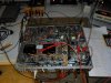
1. All wired up for testing of the stock control section.

2. A 200 Hz square wave passing through the complete control section of the X-1000, as presented to the inputs of the power amplifiers in the unit. This is with the signal presented to the Aux 1 input, both filter and loudness switches off, volume at max, and the tone controls set for electrical flat. This pic clearly shows the effects of the permanent low frequency filter that is part of the first line amplifier stage in the original design. The tilting indicates that while basic response is good, there is significant phase distortion of low frequency signals presented to the unit.

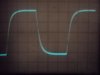
3. A 10 kHz square wave passing through the unit under the same conditions as noted in number 2 above. Note the significant rounding of the leading edge indicating a loss of HF response. While a 10 kHz square wave is a very severe test of transient and frequency response, the control section of a good preamp should still perform better than this. For those who followed the modifications I did to the 400 receiver, post #58 in that thread shows what even a passive tone control design is capable of in a properly designed circuit, with active tone control designs as used in the X-1000 capable of even better performance. The rounding is largely caused by the signal passing through the HF filter circuits, even though they are turned off.

Both of these scope pics basically illustrate the "Fisher Sound", as the result of a tailored frequency response at both ends of the audio spectrum. Very pleasant and listenable, but missing fine detail and definition at the frequency extremes. Back in the day, program sources had such inherent limitations that this was not an issue. But with today's wide band program sources, re-engineering the control section for a truly flat response over the whole of the audio spectrum will add measurably to accuracy and dynamic response of the unit's overall performance.

So now the work will start, with pics updating the progress as it is made.

Dave
 

Attachments

  • Stock X-1000 Control Section Frequency Response 001.jpg
    Stock X-1000 Control Section Frequency Response 001.jpg
    93.2 KB · Views: 67
  • Stock X-1000 Control Section Frequency Response 002.jpg
    Stock X-1000 Control Section Frequency Response 002.jpg
    28.2 KB · Views: 49
  • Stock X-1000 Control Section Frequency Response 003.jpg
    Stock X-1000 Control Section Frequency Response 003.jpg
    44 KB · Views: 45
Update

One other good result from the redesign of the control unit, is that the hard to get and expensive old production 7247s will now no longer used. In their place will go ECC82s which are much more plentiful and economical.

The other executive decision that was made is to eliminate all the wiring to the jack for connection of the Remote Volume Control option. This wiring involves significant lengths of shielded cable, which always works against good HF response. Since all of the circuits supplying signals to and from this jack are being reworked anyway, removing the cabling to and from the jack involves only a little more work, makes for a cleaner under hood appearance, and serves to further enhance signal detail.

A couple of pics thrown in:

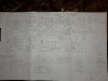
1. By now, the schematic page is marked up with almost as many notes as there is actual schematic drawing.

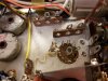
2. The original wiring for the Channel B 7247 second stage line amplifier and tone stage driver has all been removed now, and is ready for install of the new line amplifier design, which should start tomorrow.

I plan on installing the complete revisions/modifications into Channel B first. This will then allow a direct side by side performance comparison with the original design in Channel A at any point in the installation process.

Dave
 

Attachments

  • Start of Revision Installation 002.jpg
    Start of Revision Installation 002.jpg
    66.5 KB · Views: 70
  • Start of Revision Installation 001.jpg
    Start of Revision Installation 001.jpg
    92.5 KB · Views: 73
I have an electronic Dymo label maker. I will order another clear with black lettering roll of tape to update the silk screen upon the unit's return.

What's not obvious on that schematic picture is that I had the original schematic from Buglegirl's later version of the X-1000 schematic blown up by a local printing facility. That schematic page is something like 36" x 28".
Boy am I glad that I did that now.
The schematic I had for my early version was one taken from the service manual copy I had. It spans three printed pages and I'd taped them together.

If Dave doesn't make a copy for himself, I'll take that one to the local print shop and send a copy or the original markup back to Dave.
 
Eduarsan,
Thanks for the offer. We (the collective Fisher fans) may want your assistance for a more popular project later.
I don't believe that this integrated amp had enough units made that change hands regularly to justify a revised schematic. I've been aware of less than a dozen owners on this forum since I arrived in 2008.
There have been that many new 400 or 500-C owners this year alone.
If Dave feels differently, I'm sure he'll chime in.
Don
 
New Line Stage

Today, I was able to install the new line amplifier design into Channel B. The new line amplifier is a self contained two stage design that uses a single ECC82 in place of the 7247 that Fisher used as one of two tubes in the stock line amplifier design. Being a two stage design, the new line amplifier inherently does not invert phase, while using only a single socket, allows a socket to be freed up in each channel and re-purposed for Recording Output and Preamplifier Output jack buffer responsibilities.

The new line amplifier retains the same input impedance as the specification of the original design, and matches the gain of the original line amplifier within better than .5%. For all intents and purposes then, the modified X-1000 will interact with external source components as if nothing had changed.

The frequency response of the new line amplifier is superb, displaying a very flat frequency response to 100 kHz. As explained earlier, for accurate reproduction of square waves, the circuit passing them needs to have a flat response from 1/10th of the fundamental to X10 the fundamental. As such then, 10 kHz square waves at the output of the new line amplifier design look virtually identical to those going in, which is very high performance indeed.

On the low end, there will always be some phase shift when RC coupling used. However, the actual response of the new design is flat to below 20 Hz, with only slight tilting of 200 Hz square waves, which is of no significance. Distortion up to 5 vac rms at the output of the line stage is unmeasurable for all intents and purposes, over the entire audio bandwidth. The X-1000 power amplifiers only take a 2.0 vac signal to develop full power output.

In contrast to the original line stages with their various filter circuits hung on them and spread out over two tubes, this is greatly improved performance. When the tone stage is included in the amplification chain, performance is notably better than with the stock line amplifier design, but the tone stage still presents its own response limitations. Performance over the 20 Hz to 20 kHz audio bandwidth is acceptably flat, but HF transient response is notably reduced when the tone stage is included. As a result, the new design -- which has these controls normally out of the signal chain -- will display the added benefits of both the new line amplifier design, as well as that from removing the limitations of the tone stage.

Up next is removing the rest of the old line amplifier and Recording Output mixer stage wiring, in preparation for installing the buffer circuits for Channel B.

For now, a few pics to show what's going on:

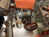
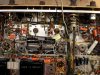
1. A shot of the new Channel B line amplifier looking in from the side of the chassis.

2. And from the rear of the chassis.

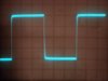
3. 10 kHz square waves at the output of the new line amplifier design leaves little to discuss.

4. AFTER passing through the tone stage, this 2 kHz square wave is greatly improved over similar stock design testing, but still shows the loss of high frequency detail by way of the rounded leading edge of the wave -- which only deteriorates further with increasing frequency. There is little within the stock design of the tone controls that can be done to improve upon this performance -- other than bypassing them altogether -- which is what the new design normally does, unless the tone controls are elected to be included in the circuit. With the controls bypassed, it results in the waveform from #3 above, clearly showing the gains in transient performance to be had -- particularly because the frequency of the waveform in #3 above is five times that of the waveform shown in this pic . Therefore, making the tone controls an option to be included only as needed was a very good feature to include in the new design.

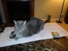
5. With large modification projects like this, I like to call in my trusted engineering partner to double check my work. Here he is hard at work, really getting on top of things. Without his invaluable input, projects such as this simply would not be possible!

Dave
 

Attachments

  • New line stage 001.jpg
    New line stage 001.jpg
    63.1 KB · Views: 72
  • New line stage 005.jpg
    New line stage 005.jpg
    44 KB · Views: 51
  • New line stage 004.jpg
    New line stage 004.jpg
    29.7 KB · Views: 56
  • New line stage 003.jpg
    New line stage 003.jpg
    79.2 KB · Views: 73
  • New line stage 002.jpg
    New line stage 002.jpg
    76.8 KB · Views: 76
Buffer Stages

The remains of the first stage of the original Channel B line amplifier, as well as the components for the stage supporting the phase reverse feature have all been removed now to make way for the new Channel B buffer circuits. This area represented a very busy portion of the original design, which also included the low frequency filters (both permanent and switchable), and resulted in a very densely packed area component wise.

Once the buffer circuits are installed, that will then allow all the new Channel B jack connections to be made, allowing the Recording Output and Preamp Output/Power Amp Input jacks to all be finished out and functioning for that channel as well.

At that point then, it will be interesting to do some critical listening to the unit, because with other than the front panel Phase Reverse, Low Filter, and High Filter switches no longer functioning in Channel B, all other front panel controls remain fully operational in both channels -- including the filter switches in Channel A as well (the Phase Reverse switch only affected Channel B). In essence then, Channel A will still represent the complete, but stock control section design with all its various filter circuits intact, while Channel B will represent the new control section design using the new high performance line amplifier installed. At this point, both channels are still operating through the tone stages (meaning both channels are phase correct to each other, with both channels inverting absolute phase), so this would be a completely fair and valid test to compare the performance of the two control section designs head on.

Additionally, this step-by-step walk through the entire unit continues to be worthwhile time spent: In examining how the new buffer stages would be connected into the existing B+ distribution circuits, it was discovered that during some past under hood work, the tone control stages were connected to the wrong B+ taps, allowing less filtered B+ to power these stages. While this did no damage and still allowed the stages to operate to their capability, it none-the-less helped to contribute to "setting off" the original motorboating problem, since such a connection resulted in less decoupling for these stages from the power amp section.

Pics include:

1. A close up of the stages cleared out as discussed above, ready for installation of the new buffer circuits for Channel B.

2. A more general pic of the entire control section of the X-1000. From left:

A. The (still installed) Channel A 1st stage line amplifier and Center Channel Recording Output summing amplifier stages.

B. The cleared out section originally containing the Channel B 1st stage line amplifier and Phase Reverse function stages.

C. The (still installed) Channel A 2nd stage line amplifier and CF driver stages.

D. The newly installed complete Channel B line amplifier stages.

E. The original tone control stages.

And the work continues. More to follow of course......

Dave
 

Attachments

  • Buffer Stages 001.jpg
    Buffer Stages 001.jpg
    100.1 KB · Views: 56
  • Buffer Stages 002.jpg
    Buffer Stages 002.jpg
    132 KB · Views: 58
Details can always be the hardest part of any project to hammer out, but are so important in determining the ultimate quality achieved in the end.

This morning has been spent addressing little details that must be addressed before work on other bigger building blocks can continue:

1. How the new buffer circuits will be connected into the existing power supply so that the current draw remains balanced. The X-1000 uses a semi dual-mono approach to distributing B+ through out the amplifier. There are two main distribution branches that serve to power the majority of each channel separately, but some functions in both channels are powered from one branch, while other functions in both channels are powered from the other branch. In the end, it all pretty much balances out. But removal of the old circuits and installation of the new ones can upset that balance if not done correctly, so it is an important detail to address.

2. Shielded cable. The X-1000 contains seemingly hundreds of miles of the stuff. With the re-engineering of the control section, some of it has to be removed, while other sections have to be re-purposed and/or rerouted to accommodate the new features. But it's not that simple, as the new features require new lead lengths as well to accommodate the new circuit layout. Determining what wires then ultimately come out, what wires stay in place connected as is, and what wires stay in place but are now used for a different purpose -- all while addressing the needs of the new layout -- takes significant planning. Addressing these details ahead of time will ultimately help minimize the overall effort required to get the various connections of all these leads correct.

3. Powered center channel speaker output. This is going to be eliminated as previously discussed, so as to have the common output terminals of both channels reference ground. This will allow common ground speaker switching systems and cabling to be used, where as the stock configuration prevents this. But then there was the 1 AM revelation this morning that the stock power amplifier section in the X-1000 also changes signal phase. UGH!!! -- And all because of that damnable powered center channel speaker output design, too.

Actually, it doesn't cause any real problems because when the stock output configuration is converted to a traditional one (by removal of the powered center channel output), the phase issue will also be resolved in the process. However, it does mean that my initial assessment that the X-1000 changes absolute phase in stock form is incorrect: If the stock control section changes phase (it does), but the power amplifier section also changes phase (yep, it does too), then we're right back where we started with no net change in phase. However, if you separate these two sections in stock form, then you end up with each section inverting phase, making their standalone capabilities (via Preamp Output/Power Amp Input jacks) compromised.

Since the new control section line amplifiers do not change phase, it means that the nice feature of converting the Common output terminals to represent ground level is now a required change as well. Doing this will ensure that the finished modified unit will not change absolute phase -- and importantly -- that if each section is used in stand alone fashion via the aforementioned jacks, that neither section individually changes phase either.

But then there's the silly headphone jack on the real panel that is wired in reverse phase from the speakers in the stock design as well. More details. I will be so glad when all the phase issues have been dealt with! As the saying goes however, the devil is always in the details.......

Ultimately, I have no illusions of grandeur that anyone with an X-1000 would want to incorporate all of the changes going into this unit. This effort has gone way, way beyond typical dependability servicing, general enhancements, tweaks, or modification efforts, but has really become a truly full blown major redesign of the unit. It didn't start out that way. But as the possibilities of new and more useful features became viable, the implementation of them is much like the proverbial thread you pull on: The issues involved in dealing with one feature lead to issues with a another, and so on, until at the end of the project, there is virtually nothing untouched or that hasn't significantly changed from the original design -- but all done so that the new features are implemented properly, so as to work correctly. Which begs the question then: When is a Fisher still a Fisher?

In this case, I like to think that this X-1000 is still very much a Fisher, in that it will produce the best possible performance as determined by the most basic elements of the design (the transformers), with the most desirable features relevant to today's audio world, and all work in classic Fisher-like style: noiselessly, cleanly, smoothly, dependably, and powerfully -- and all while still retaining the original look as built by Fisher. In short, I would like to think that this re-engineered X-1000 represents what Fisher themselves would have produced, had they actively produced this model for today's audio market. Since the final product will still very much represent the qualities that Avery Fisher strove to achieve, then I think his name still applies.

For now however, the work goes on.......

Dave
 
Last edited:
I find the way Dave's mind works interesting. One of the first things we discussed was whether I wanted this X-1000 to remain an X-1000 per se, or was I comfortable with the changes.
Dave told me that he'd been offered one locally and that, if he decided for getting the unit, that it was clean enough to remain stock.

On this one, because the front panel has already been redone, I thought that a change was warranted because it will never pass for stock anyway. As GoldenPath would say, if it can't stay stock, then make it a masterpiece that optimizes what the unit is capable of doing, rather than keeping it stock to fulfill the designer's intent.
I couldn't agree more.
This will be a masterpiece.

Oh, and Dave, powered subs have phase switches.
Don
 
Last edited:
Weekend Progress

No new revelations to report. Just solid progress with a few pics to show current status:

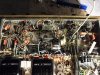
1. The cleared out section with the completely empty tube socket will be where the new control section output buffer circuits will be installed (each section of the ECC83 tube serving one channel) with their output signals ultimately terminating at the new Preamp Output jacks.

2. Back at the back panel though, even though progress was being made with the shielded cabling, the secondary wiring of the output transformers was driving me nuts. Every indication is that the OPTs had been removed at some point, for some reason, because I can't believe that Fisher would have wired this unit that way. Not only that, with the power of 50 watts RMS per channel available, note the size of those those transformer secondary wires -- except that the Common and 4 ohm terminals are wired to their respective transformer leads with 20 Ga wire! It looks like Fisher type wire, but entirely too small for the power this amplifier represents. Since I was back at the back panel again anyway to finish up shielded wiring, I might as well have at the output wiring while I'm there.

3. New, properly color coded wire of the correct gauge is now laid in place to connect the Common and 4 ohm output terminals to their respective transformer leads. The wiring at the output terminals was removed and reinstalled in a manner that Fisher likely would have.

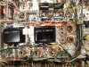
4. Back at the driver circuits of the power amp, the mass of coupling caps had to be removed to access and provide for the Power Amp Input circuits. Concern had been noted earlier that with all the coupling caps glued together as they were, that HF response was suffering. With them now separated, once the Power Amp Input jacks are connected, then the power amp sections will be retested for response and power -- the latter because wiring is now in place that can actually handle 50 watts of power without significant loss.

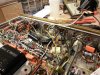
5. The new black and green leads are temporarily tacked in place at the transformer end so that the measurements mentioned in #4 can be conducted on the stock power amplifier circuits. Ultimately, this end of the green and black leads will be reconfigured when permanently installed to resolve the phase reversal that takes place in the power amplifier sections of the X-1000. Other than those connections awaiting their new home, all of the power output stage and back panel wiring work across the entire back of the amplifier is now finished up as shown. The vast majority of it has all been redone.

The tests on the power amp section will also now clearly show the performance of the NFB loop and stability circuits for what they are (since the coupling caps are all unglued from each other) -- and allow for any adjustments/modifications to be made for improved performance. This check is also necessary since the output transformer wiring is being revised to correct the phase reverse issue in this section.

Once the control section output buffer circuit is complete for Channel B (the one I am principally working on), then the unit as is will actually let me listen to the unit in stereo with Channel A still basically stock, and Channel B using the new line stage amplifiers and buffer output circuit. Should be an interesting test.

Dave
 

Attachments

  • Rear Panel Output Wiring 001.jpg
    Rear Panel Output Wiring 001.jpg
    123.8 KB · Views: 61
  • Rear Panel Output Wiring 002.jpg
    Rear Panel Output Wiring 002.jpg
    135.3 KB · Views: 61
  • Rear Panel Output Wiring 003.jpg
    Rear Panel Output Wiring 003.jpg
    157.6 KB · Views: 55
  • Rear Panel Output Wiring 004.jpg
    Rear Panel Output Wiring 004.jpg
    133.7 KB · Views: 58
  • Rear Panel Output Wiring 005.jpg
    Rear Panel Output Wiring 005.jpg
    142.7 KB · Views: 56
Back
Top Bottom