

You are using an out of date browser. It may not display this or other websites correctly.
You should upgrade or use an alternative browser.
You should upgrade or use an alternative browser.
Fixing up and restoring a Kenwood KA-5002 integrated amplifier
- Thread starter Wombaton
- Start date


eizner23
Super Member
^ Agreed. You could reroute the two output wires from low level amp directly to amp board input to bypass high/low filters for troubleshooting. I left mine permanently bypassed to reduce signal path since filters were never used.
Another common semiconductor component: ripple filter Qk1.
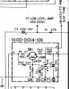
Another common semiconductor component: ripple filter Qk1.

Wombaton
Active Member
I thought that since I keep hearing the noise with 'PRE/MAIN' switch on 'separate,' the high and low filters are not the problem.
With the switch on 'separate,' the signal goes directly from the main input and into the main amp. Or could the noise from previous stages still bleed in?
Also, I do not see any 'common components' in the filters. But bypassing them temporarily is a good idea. I am planning to replace caps and transistors on the filters anyway, but hope to do it after eliminating the primary source of noise.
I did not think about the ripple filter, though! Qk1 is 2SC971(B), so I marked it as a 'keeper' initially, but now will definitely check it out. On my amp, the ripple filter had been recapped (with original Qk1 left in place by the looks of it), so who knows what might have happened in the process.
One other idea: could D2 (10D-1) also be a potential source of 'symmetric' noise in the outputs?
Big THX for the advice and brainstorming.
W.
With the switch on 'separate,' the signal goes directly from the main input and into the main amp. Or could the noise from previous stages still bleed in?
Also, I do not see any 'common components' in the filters. But bypassing them temporarily is a good idea. I am planning to replace caps and transistors on the filters anyway, but hope to do it after eliminating the primary source of noise.
I did not think about the ripple filter, though! Qk1 is 2SC971(B), so I marked it as a 'keeper' initially, but now will definitely check it out. On my amp, the ripple filter had been recapped (with original Qk1 left in place by the looks of it), so who knows what might have happened in the process.
One other idea: could D2 (10D-1) also be a potential source of 'symmetric' noise in the outputs?
Big THX for the advice and brainstorming.
W.

Hi Wombaton - Great thread!!! A friend just brought me his KA 5002 with a dead channel (recent purchase for him). This is very helpful. I'm a noob at repair, but pretty handy overall. I read you could not find a Service Manual, but it looks like one on your bench in your first post. Did you find one eventually? HFE still doesn't have one listed. Thanks for all the useful info and homework you're sharing!
Wombaton
Active Member
@eizner23: I would like you thank you for your help again. I think, since we managed to trace the source of the noise to three possibilities, I can just check all of them and see what happens. My recapping kit (including the semiconductors) recently arrived from mouser, so I hope to have some meaningful updates soon. For now, most of my free time is going into yard work 
I also found this interesting comment (review by boke) on the HFE page for KA-7002:
https://www.hifiengine.com/manual_library/kenwood/ka-7002.shtml
This review claims that a dying Zener was the source of intermittent popping and hissing noise. Since there are similarities in the main amp boards for KA-5002 and KA-7002, I think I will look into replacing the Zener diode first and leave the ripple filter for later. Your replacement for ZB1-14 looks great (THX for the info)! I got the Nexperia one (14.1 V, 1-1.3 W @+-5%), which I think should also work. I was also fortunate to score a whole collection of KA-4002 and KA-5002 PCBs and other stuff cheap off eBay, including another original ZB1-14, 5T-31 thermistors and STV-3 MTJ.
@Designr10: THX for your kind words and welcome to the community. Honestly, I am not at all sure how useful my KA-5002 homework is going to be to others, but I based it off of a good example in the KA-4002 restoration thread (capacitor coupled KA-4002 seems like a much more popular choice for tinkering). I will have to do an update on my google drive Excel sheets at some point, as I had to make a few changes while purchasing all that stuff at mouser.
Regarding the KA-5002 service manual, you are correct -- I got one, but it is not a HFE manual. I had to purchase a printed copy (which is truly excellent quality) from Rick Stout at
http://www.stereomanuals.com/
Or if you are very lucky, you can score one off of eBay. I have to add that I really love how Kenwood manuals are laid out, compared to ones from SONY and Pioneer.
Regards,
W.
I also found this interesting comment (review by boke) on the HFE page for KA-7002:
https://www.hifiengine.com/manual_library/kenwood/ka-7002.shtml
This review claims that a dying Zener was the source of intermittent popping and hissing noise. Since there are similarities in the main amp boards for KA-5002 and KA-7002, I think I will look into replacing the Zener diode first and leave the ripple filter for later. Your replacement for ZB1-14 looks great (THX for the info)! I got the Nexperia one (14.1 V, 1-1.3 W @+-5%), which I think should also work. I was also fortunate to score a whole collection of KA-4002 and KA-5002 PCBs and other stuff cheap off eBay, including another original ZB1-14, 5T-31 thermistors and STV-3 MTJ.
@Designr10: THX for your kind words and welcome to the community. Honestly, I am not at all sure how useful my KA-5002 homework is going to be to others, but I based it off of a good example in the KA-4002 restoration thread (capacitor coupled KA-4002 seems like a much more popular choice for tinkering). I will have to do an update on my google drive Excel sheets at some point, as I had to make a few changes while purchasing all that stuff at mouser.
Regarding the KA-5002 service manual, you are correct -- I got one, but it is not a HFE manual. I had to purchase a printed copy (which is truly excellent quality) from Rick Stout at
http://www.stereomanuals.com/
Or if you are very lucky, you can score one off of eBay. I have to add that I really love how Kenwood manuals are laid out, compared to ones from SONY and Pioneer.
Regards,
W.
Last edited:
Wombaton
Active Member
A brief update, since I had a bit of time to poke around the main amp board earlier today. All I did was replacing the ZB1-14 Zener (Dq9) with a new one from Nexperia and voila -- all the popping / crackling noise is gone. Need to listen to the amp some more to confirm, but my initial impression after a 20 min session is that the problem is solved. As we have discussed here, KA-5002 is full of components that can make noise. However, right now, with ZB1-14 plucked out, my amp is being surprisingly quiet -- at least on line inputs.
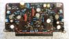
The picture below shows the main amp board, with the pesky Zener ZB1-14 diode outlined in red:

BTW, I checked the extracted ZB1-14 Zener with my TC-1 tester. It is still recognized as a 'diode,' but its parameters measurements are unstable: I did multiple runs and they drift quite a bit.
I guess, I can now cautiously proceed with recapping. +1 for little furry critters.
W.
The picture below shows the main amp board, with the pesky Zener ZB1-14 diode outlined in red:
BTW, I checked the extracted ZB1-14 Zener with my TC-1 tester. It is still recognized as a 'diode,' but its parameters measurements are unstable: I did multiple runs and they drift quite a bit.
I guess, I can now cautiously proceed with recapping. +1 for little furry critters.
W.
Last edited:
This is great info. I fixed a dead right channel by cleaning the preamp/ amp bypass switch on the back panel. But definitely have the hiss and crackle noise from the main amp side. I’ll order a diode and swap. I’m not being very scientific about this but your experience is really helping me look in the right places.

Semanon
Super Member
Looks like you replaced all the resistors with metal film. Did you hear a difference? With the removable boards, it seems like that’s not a huge effort if there is some benefit. Recommend?here is a snap of one of mine polished up.
View attachment 2044375
eizner23
Super Member
Lower noise, I can hear a difference at higher volume, less distortion.Looks like you replaced all the resistors with metal film. Did you hear a difference? With the removable boards, it seems like that’s not a huge effort if there is some benefit. Recommend?
Wombaton
Active Member
That amp board sure did go thru some redesigns I havnt seen the earlier versions , here is a snap of one of mine polished up.
View attachment 2044375
@eizner23: This board does seem to be a later version and by its busy looks I'd assume it is from KA-7002, or am I off the ball here?
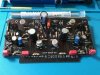
Here is my main amp board after the recap; the photo was just taken earlier today. This one is an early version, not much crowded. I used Wima film for 1uf caps, refreshed only the high-power resistor and let the other resistors be. A few ones I could measure (out of circuit) while working on this board were dead to specs. On the other hand, the old electrolytics were way out of spec. I did not change the trimmers, will do that later. The amp is still alive and behaving quietly after this upgrade.
It is most convenient to have a removable board like this one. Reminds me of old PC desktop motherboard connectors, while this design is of course older than the PC itself. Now I moved on to the low and high filter boards, which are not removable (pity!) and a much bigger pain to work with. That is unless one bites the bullet and unsolders all the connectors.
W.
Wombaton
Active Member
This is great info. I fixed a dead right channel by cleaning the preamp/ amp bypass switch on the back panel. But definitely have the hiss and crackle noise from the main amp side. I’ll order a diode and swap. I’m not being very scientific about this but your experience is really helping me look in the right places.
@Designr10: I would still recommend being somewhat scientific about noise. It is good housekeeping to change out the old Zener, but there is no guarantee that your noise is the same as mine. As discussed above, many other components here that can get noisy. So in my case it helped making some very basic determinations about the noise to narrow down the possible culprits:
(a) Is the noise symmetric in both channels or not?
(b) Is it affected by the position of the volume / balance knob or not?
(c) Does it stay or go if I flip the pre/power amp switch?
HTH,
W.
Wombaton
Active Member
Incidentally, here is a 'backup' main amp board that I got off eBay. Although the PCB is still marked as X07-0027-00, it is populated differently, compared to my primary board shown in post #33. There are quite a few extra diodes and resistors present here, and it seems like Q13 and Q14 positions had been occupied by transistors. There are also resistors mounted on the foil side. My primary board has none of that.
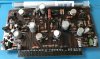
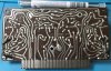
As is clearly visible, R32 died a fiery death and took who knows what else with it. I am not sure where this board actually comes from. KA-5002 manual has the 0027 variant that looks like my primary board and then a 1020 variant that looks very different. KA-7002 manual has a 0027 variant that is different from both of these boards (it has Q7, Q8 positions actually occupied with transistors instead of capacitors). Could this be some transitional type between 0027 and 1020? Would be interesting to plug it in and listen to it if it weren't so thoroughly dead. Since I have no documentation for this type, I am not sure how to restore it.
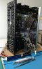
Also, this is the view of the restoration process for the high and low filter PCBs. I managed to rotate them 180 degrees without removing any connector wires, which provided limited assess to all surfaces. Still, this is a good exercise in developing ambidexterity, as occasionally I have to hold my soldering iron with my left hand and tweezers with my right.
W.
As is clearly visible, R32 died a fiery death and took who knows what else with it. I am not sure where this board actually comes from. KA-5002 manual has the 0027 variant that looks like my primary board and then a 1020 variant that looks very different. KA-7002 manual has a 0027 variant that is different from both of these boards (it has Q7, Q8 positions actually occupied with transistors instead of capacitors). Could this be some transitional type between 0027 and 1020? Would be interesting to plug it in and listen to it if it weren't so thoroughly dead. Since I have no documentation for this type, I am not sure how to restore it.
Also, this is the view of the restoration process for the high and low filter PCBs. I managed to rotate them 180 degrees without removing any connector wires, which provided limited assess to all surfaces. Still, this is a good exercise in developing ambidexterity, as occasionally I have to hold my soldering iron with my left hand and tweezers with my right.
W.
eizner23
Super Member
Interesting to see the earlier models. My board was from a later model KA-5002. I uploaded the service bulletin to hifiengine that shows the difference variances
https://www.hifiengine.com/manual_library/kenwood/ka-5002.shtml
https://www.hifiengine.com/manual_library/kenwood/ka-5002.shtml
@Wombaton Good advice. I was being a little tongue and cheek, and did do some basic sleuthing as suggested. I do have noise in both channels, not affected by Vol or Bal, and unaffected by the amp selector switch on the back. So it seems to be in the main amp side, and some component common to both channels. My diode showed up last night so we will see how lucky I am, if I can sneak away for a few!
Wombaton
Active Member
Then, according to the service bulletin, the (burned) main amp board shown in post #35 is from an older KA-5002 with S/N < 240,000.
My KA-5002 unit has S/N ~ 330,xxx and my 'primary' main amp board (post #33) looks appropriate for that S/N.
Interestingly, the service bulletin says that different main amp boards are not interchangeable, so I guess I should not play with that.
W.
My KA-5002 unit has S/N ~ 330,xxx and my 'primary' main amp board (post #33) looks appropriate for that S/N.
Interestingly, the service bulletin says that different main amp boards are not interchangeable, so I guess I should not play with that.
W.
@Wombaton I'm eager to learn so I hope you can help with my latest efforts. I checked the DC offset on the 5002 and found this: L- 39mv R- 72mv. Unless this amp has circuits that make this normal, we are a long way from the best readings (less than + - 15 Mv), right? I did get a Service Manual (thanks for the pointer), but it is not clear to me from page with alignment procedures if the DC offset VR's are identified, or if there are any for this. Seems to only show how to set center voltage VRq1,2 (unless this is it) and idling current VRq3,4, across the power transistors. Clearly trying to learn my way around here, and if you have some advice, or direction here I would greatly appreciate it. I do understand there is great opportunity for things to go badly wrong here, and have studied enough to know not to go twisting pots without some clarity on what your doing. BTW I have invested in a LCD oscilloscope, freq generator, and 8ohm dummy loads to check the adjustments outlined in the manual. Any guidance is welcome.