• The move to the new server is done. There are some software and database maintenance updates in process. This has us passing the hat around to help out. We appreciate any donations. Seriously, even a dollar helps. The payment page may be found here - https://www.audiokarma.org/support.html

Fixing up and restoring a Kenwood KA-5002 integrated amplifier

If you use a triac, buy the one with solder lugs. It's $2 to $3 more, but is so much easier to work with that it's worth it.

For me and the lamps, at some point I'm going to get the itch to modify these amps again, and leaving the LED til later gives me something to do when the work bench is calling. It took me 5 or 6 iterations to get the brightness right on one unit I worked with. So I expect some trial and error (brightness, color temp, dispersion, etc.). It's a 'finish' and aesthetic issue for me.
Screenshot_20201227-200902~2.png
 
Last edited:
Looking good W. I will stay tuned for your variac installation. I left the bulbs in- its tough to find an LED that will fit inside those round metal lamp shields.
 
If you use a triac, buy the one with solder lugs. It's $2 to $3 more, but is so much easier to work with that it's worth it.
View attachment 2079241

Actually, I do not mind working with the 'L' (rather than 'J') package if the leads are long enough and if I can properly insulate the joints. I find regular electrical tape and heat-shrink tubing lacking in neatness and versatility. I wonder if liquid / brush-on 'electrical tape' solutions are a good option? If yes, any particular brand, like Blue Magic, Star Brite or something else?

For me and the lamps, at some point I'm going to get the itch to modify these amps again, and leaving the LED til later gives me something to do when the work bench is calling. It took me 5 or 6 iterations to get the brightness right on one unit I worked with. So I expect some trial and error (brightness, color temp, dispersion, etc.). It's a 'finish' and aesthetic issue for me.

Since it looks like many 70s KA models are running selector lamps off of 7.5V AC, it would be nice to develop a generic recipe for a LED upgrade with pleasing aesthetics. I surely hope that I will be able to experiment with this a little bit later -- that is, as long as I get LEDs that would properly fit into the lamp sockets.

W.
 
Looking good W. I will stay tuned for your variac installation. I left the bulbs in- its tough to find an LED that will fit inside those round metal lamp shields.

Using a variac (rather than a triac :D) is another great solution to defeat power switch arcing. I would do this all the time if it weren't so clunky. Since the current inrush happens gradually on a variac, arcing never occurs.

Actually, I always test the amp after making a new batch of upgrades by doing a DBT check and then putting it on a variac and raising the voltage slowly while monitoring the current. That is why arcing was such an unpleasant surprise when it first happened. You do the variac test and everything looks peachy. Then you plug into a regular AC outlet, press the power switch and get a mighty 'pop' and a puff of smoke coming out. For a moment I thought I was a goner together with my amp :D.

W.
 
I find regular electrical tape and heat-shrink tubing lacking in neatness and versatility. I wonder if liquid / brush-on 'electrical tape' solutions are a good option? If yes, any particular brand, like Blue Magic, Star Brite or something else?
Shrink worked well for me. A little bumpy, but on my CA-810 it gets buried anyway.
20201003_230251447_iOS.jpg 20201003_231240450_iOS.jpg
(Ignore the soldering iron burn on the blue wire. Must have been at the factory...couldn't have been me.)

Since it looks like many 70s KA models are running selector lamps off of 7.5V AC, it would be nice to develop a generic recipe for a LED upgrade with pleasing aesthetics. I surely hope that I will be able to experiment with this a little bit later -- that is, as long as I get LEDs that would properly fit into the lamp sockets.
Agreed. My goal would be to replicate the brightness and visual aesthetics of the originals.

Very nice work, W.
 
Last edited:
I very much appreciate the words of encouragement and the pictures of shrink-wrapped triac. Although, I had to ponder for a while how blue piece of shrink tubing, covering two wires, had been applied. Anyway, I have some 2mm(before)/1mm(after) shrink tubing I can experiment with.

THX,

W.
 
Inquiring minds want to know....Slip the shrink on both wires before soldering to the triac AND before soldering brown wire to the switch. White wire leads to the unswitched outlet.

In my case: 1) solder to the switch; 2) try to figure how to get the heat shrink on; 3) curse lightly; 4) unsolder the wire to the switch; 5) put both wires through the heat shrink...you get the picture. DIY makes fools and heroes of us all.
 
As I am waiting for parts to come in to finish updating the breakout board and do the triac mod to the power switch, I am, as usual, pondering a few questions -- some of these in retrospect to figure out what I could do better in my next project. Any comments from the community would be most welcome!

(1) For electrolytic cap replacements I made, in many cases the size and lead spacing of the new cap would not be perfectly matched to the original. Therefore, I got some new electrolytic caps floating over their host PCB instead of their bottoms being in firm contact with it. Is that an Ok thing for a restomod, or sloppiness that should be avoided? Me thinks, avoiding it completely would be tough, as I either have to measure out every old capacitor in advance (wasted time) or must have a huge assortment of replacement caps in different form factors (wasted $$$).

(2) Reading a different AK restoration thread, I saw a discussion of upgrading big filtering capacitors, which would be 2200 uF C1 and C2 in the case of KA-5002. The main message was that these caps cannot be bumped up in capacitance too much without ill consequences, as the rest of the circuit will experience too high of a current needed to charge these caps -- and eventually some other components, like diode rectifiers, could get fried. I agree with this message and therefore I think that my 2x bumping of C1/C2 to 4700 uF might have gone too far, especially since KA-5002 diode bridge is an unobtanium component. Maybe a more conservative 1.5x capacitance increase would be a better compromise reliability-wise? On the other hand, the KA-5002 diode bridge is built like a tank and rated for 5 Amp current (if I am not mistaken). Seems like a big overkill for an amp pushing 200 W at full power with a 2 Amp main fuse. So maybe, in this particular case, the bridge can handle the increased current needed for the fat new caps? Or am I missing something?

(3) For implementing the triac mod, I figure I can cut into the power switch circuit in two possible places: [a] close to the switch, which probably requires its removal, and [b] close to the unswitched AC outlet on the back where the power cord is attached. Any comments on which location may be preferable? My naive impression is that option [b] is much less of a fuss (unless you are disassembling and cleaning the switch anyway), but I usually see option [a] implemented on other AK threads.

(4) Finally, may people favor adding snubber caps (e.g., 0.1 uF) in parallel with some beefy caps here? I've seen this done on output capacitors in capacitor-coupled amps (not this case), as well as on power/filtering caps. Not sure of the benefits of the latter, but it seems like it would not hurt anyway. Any ideas?

THX,

W.
 
Got the breakout board completely redone with 1N4005 diodes and Nichicon UKL caps I had in my stash:

IMG_1126.jpeg

No issues, everything works. The 'before' state is shown in post #60 above.

The triac mod for the power switch is next. Got all the parts and even found a hole in the chassis where I can mount the triac. Regarding item (3) in my previous post, I decided to bite the bullet and go from the front, which will involve removing the face panel and the power switch. I guess, some extra cleaning for both would not hurt.
 
Still tuned to this channel:
Much appreciated your documentation and spreadsheets.
Wish all re-builders were doing this,
if only the AK website could help with standard form DB inputs for parts / rebuilds and link it to a voting system for most successful.
Now THAT would be another great incentive for being a subscriber.

Regarding the KA-5002, Something in me is saying your are somewhat overdoing it but I understand, its part of the fun.
Would be great to compare this effort vs another copy serviced the "minimal effort way = electrolytic / suspicious diodes / noisy transistors.
 
@Loalaweiter: I do appreciate the feedback on this effort! I realize that what is going on here would be interesting mostly to beginners like myself. But as a practitioner of 'scientific method,' I value organizing data and taking notes of any important details. I usually do not remember what I was doing and thinking a few days ago, and having notes and comments neatly stacked in this thread helps a lot. I am also glad to hear that my Excel sheets seem to be useful.

Now, regarding minimal effort vs overdoing, I would consider this restoration being closer to minimalist in its extent, with just a few extra items (like suspicious resistors) added to the list above. I have seen a number of restorations in AK where all semiconductors (except maybe outputs) are replaced by default and I have seen some restorations where PBCs are stripped completely and rebuilt with new components. I guess, it is whatever bakes your cookie.

Cheers,

Wmbtn
 
I repaired one of these amps, mostly by recapping. I see no need to replace the bridge rectifier if it is not damaged. They either work or they don't, and they don't slowly degrade the way an electrolytic cap would.
 
The clean power switch blunder

So, in preparation for doing the triac mod, I disconnected the power switch from the chassis. Here we go:
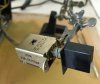
IMG_1128.jpeg IMG_1129.jpeg IMG_1130.jpeg IMG_1131.jpeg

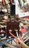
As we can see from the second image, all the wiring is hidden in a neat flexible metal jacket that is connected to the chassis at the back. The green wire connected to the two bridged contacts at the back of the switch is 'hot,' while the white and red wires connected to the middle contacts are 'load' (transformer) and 'switched outlets,' respectively.

Feeling supremely confident, I decided that it is a good idea to disassemble the power switch and thoroughly clean it from the inside. The switch came apart quickly and with no problems:
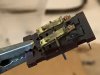
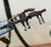
IMG_1132.jpeg IMG_1133.jpeg IMG_1136.jpeg IMG_1137.jpeg

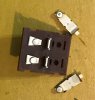
As can be seen from the first two images, that is one filthy power switch (even after deoxit application)! No wonder it was arcing. Clean, clean, clean -- with the final result shown in the last image. Note that one set of contacts is worn out more than the other.

And now on to quick reassembly of the switch -- to move on to other important business? Well, not really! As I found out the hard way, this type of switch completely refuses to come back together. See these little ball bearings and springs in the third image? They go into cylindrical openings in the white plastic piece and are held there by gravity. However, the contact plates sitting on the top cover of the switch (images 1,2 and 4) are also help in place by gravity. When the switch is reassembled, these two sub-assemblies must be sandwiched together with great precision, so that the ball bearings go right into little guiding grooves on the contact plates. A little misalignment and the springs are bent and the ball bearings get launched all over the place (good luck finding them!).

Now, after many hours of brainstorming and trying different things, I managed to put the switch back together the way it was. I emphatically recommend to the community to NOT disassemble this type of switch, but instead do as much cleaning as possible with the switch intact. Contact pads should be reachable as they are with little sanding sticks.

Here is my reassembled switch now, being wired for the triac install (more on that in later messages):
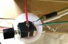
IMG_1142.jpeg

Looks like it is mortally wounded, with all the electric tape bandaged around it. It is very clean and well lubricated with deoxit gold, so I am 100% confident in its electrical performance. Not so much confidence in mechanical performance, though. It is not 100% back to the way it was originally and gets stuck a bit on turn-off. However, it is gradually improving and getting less sticky as I keep working it with lubrication.

So again, from an engineering standpoint -- excellent switch that keeps working for 40+ years while being extra dirty, but if you pull it apart it is a huge pain to get back together. That is, unless you know a bunch of special tricks. Incidentally, I found out that (in a pinch) the switch works without the ball bearings in it -- i.e., with the springs only! But with the spring tops rubbing back and forth directly against the contact plates as the switch is operated, I am sure that things get worn out much more quickly. I also figure that -- if lost -- similar ball bearings could be had on eBay for a few $$. I will actually be ordering a bunch.

Wmbtn

 
Last edited:
@Loalaweiter: I do appreciate the feedback on this effort! I realize that what is going on here would be interesting mostly to beginners like myself. But as a practitioner of 'scientific method,' I value organizing data and taking notes of any important details. I usually do not remember what I was doing and thinking a few days ago, and having notes and comments neatly stacked in this thread helps a lot. I am also glad to hear that my Excel sheets seem to be useful.

Now, regarding minimal effort vs overdoing, I would consider this restoration being closer to minimalist in its extent, with just a few extra items (like suspicious resistors) added to the list above. I have seen a number of restorations in AK where all semiconductors (except maybe outputs) are replaced by default and I have seen some restorations where PBCs are stripped completely and rebuilt with new components. I guess, it is whatever bakes your cookie.

Cheers,

Wmbtn

Really, the structured notes sharing is the thing ... I should take note and learn that from you. Maybe I'll "borrow" the template, thank you very much.
My KA-5002, after resurrecting one channel with by relay cleaning action (no sand sticks , only paper) plays warm and tired. It looks good so it would sell on eBay as "works & great vintage sound".
It's a perfect example of what I don't want in sound.
So to get it better, which parts to swap? Probably try caps first. If any transistor noise carefully swap those bad reputation ones..
Tempting to "accidentally find" another copy and apply egellings' and then your example to compare with the original but tired one and enjoy (hopefully) the reward of hours of devoted well meant labour.
By overdoing it, I meant in terms of solid return in sound quality experience, if the goals are longevity for the next 50 yrs its maybe another playfield.

I am into local amplifier brands but the mentality of people in the know is mostly to clinch onto schematics and methods and take them into the grave.
Thanks to these wide spread Japanese brands we have something common to talk about and by sharing experience more heritage will be saved for future generations that do care. By al means carry on and enjoy :-)
 
Really, the structured notes sharing is the thing ... I should take note and learn that from you. Maybe I'll "borrow" the template, thank you very much.

You are most welcome to them, as that is why I made these Excel tables accessible.
BTW, my design is based on the table used by @dlucy in his thread on KA-4002 recap.
I simply split his one large Excel sheet into multiple ones organized per individual PCBs + chassis, which is more convenient for me (less information overload).

My KA-5002, after resurrecting one channel with by relay cleaning action (no sand sticks , only paper) plays warm and tired. It looks good so it would sell on eBay as "works & great vintage sound".
It's a perfect example of what I don't want in sound.
So to get it better, which parts to swap? Probably try caps first. If any transistor noise carefully swap those bad reputation ones..

Here, my naive suggestion is to start by recapping the boards that sit in audio tract, while bypassing other stuff (like power and protection).
However, even that includes a lot of boards, some of which are not so easy to reach.
Therefore, I would start with the Main Amp board because it is detachable -- recap that and check if the sound is more to your liking.

In its current state, I do not find my KA-5002 to be particularly 'warm' and by no means does it sound 'tired' anymore.
Keep in mind that I am listening to it on my test setup, which is a crap little CD transport and a pair of (original / not recapped) KLH 33s I'd pulled out of a garbage pile.
There are a few things I still need to do before I move this amp on to the grown-up system. Got Polk Monitor 10s waiting for it.

Finally, I am sure that exploring local European amp brands is great fun. We are quite partial to local stuff as well.
E.g., I recently got a Dynaco SCA-80q off eBay (the price was right) and that unrestored little amp totally wiped the floor with my 'restored' KA-5002.
There is a US company that sells modern upgrade kits for Dynaco stuff that are supposed to improve things beyond the level of a simple recap.
Great fun it is, just have to be very careful disassembling power switches.

W.
 
TRIAC mod for the power switch

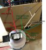
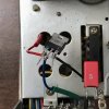
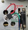
I implemented a simplified version of the mod that does not include an RC piece between MT1 and MT2, so all you need is a triac and a 100 Ohm gate resistor. Here is my wiring layout on the power switch:

triac_mod_layout.jpg

I did not have wire of the same color as Kenwood originals, but I did have proper colors for shrinkwraps. Here and below green wrap represents hot wire, white represents load wire and red -- gate wire. Note that the switch (as usual) has two independent sets of contacts. The second set operates the bank of 'switchable' AC outlets on the back panel of the amp. Here I disconnected that wire (red Kenwood original) from the switch and hid it under the black piece of electrical tape. Then both 'On' and 'Off' sets of power switch contacts were bridged.

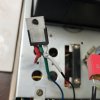
Here are some images of the triac being test fitted with wiring and then soldered and shrink wrapped:

IMG_1144.jpeg IMG_1145.jpeg

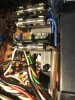
And here is the finished triac assembly bolted to the chassis with some thermal grease. I figure, people will recognize the spot where it is mounted, which is an empty area next to the diode bridge:

triac_mount.jpg

This modification works very well with no issues. If before I would hear noises (like 'slap!' or 'pop!' sounds) from the power switch on turn on, now the switch is dead quiet, i.e., all I hear from it is mechanical 'click' and nothing else. I tested the amp for ~30 min with an 8 Ohm load and volume around 11 o'clock -- the triac stays cold.

Wmbtn
 
very nice thanks for adding to the collective, and no smoke so now i can ask what is the triac part number you selected? :D
i will try the adaption in the future.
 
very nice thanks for adding to the collective, and no smoke so now i can ask what is the triac part number you selected? :D
i will try the adaption in the future.

Sorry, I guess I should add a bit more information here:

(1) TRIAC part: I used whatever is mentioned in a number of different threads describing such mods -- Littlefuse Q4025L6, which is rated for 400 V / 25 Amp current. This component comes in a number of different variations. I chose one with simple straight leads (the 'L6' version) because I do not mind them, while other AKers may prefer loopy leads (which adds considerably to the part cost). Pulling down the datasheet was most useful, as it shows where MT1, MT2 and Gate leads are located. My TC1 tester did not recognize a triac. I also got a few Q6030LH5 ones in the same order, but these are rated for 600 V / 30 Amp, which would be major overkill for KA-5002.

(2) Some thinking that went into choosing the power rating on the gate resistor. This one is 100 Ohm, but the power rating could vary depending on the maximum current amperage that needs to be controlled. Post #10 in the original mod thread sheds some light on this and provides a good rule of thumb: one W per each Amp of current. KA-5002 is rated for 200 W at full power, which gives us less than 2 Amp max current, which in turn leads to a 3W comfortable rating for the resistor. I guess, 2W will do in a pinch as well, but a more powerful amp will require a beefier resistor.


That's it! Not much left to do on this amp. Plucking out old trimmers on the main amp board now to replace them with Bourns and readjust offset / bias.

Wmbtn
 
I emphatically recommend to the community to NOT disassemble this type of switch
Most emphatically agree. Had he same overly confident approach to they same type switch on a KA-6004. Gravity is your enemy. I eventually used hot glue to hold the contact paddles in place while I painstakingly reassembled the switch, then removed the hot glue. Hours wasted, and several thoughts about parting out this sweet sounding amp.

Very nice work on the triac. How did you do the wire wrapping?
 
Most emphatically agree. Had he same overly confident approach to they same type switch on a KA-6004. Gravity is your enemy. I eventually used hot glue to hold the contact paddles in place while I painstakingly reassembled the switch, then removed the hot glue. Hours wasted, and several thoughts about parting out this sweet sounding amp.

I did tiny dabs of thin superglue on springs and ball bearings. But the most important thing was to put the switch back together in the 'ON' position, which required extra clamping. After the switch was assembled, soldering in new wiring and heating shrinkwrap burned off the superglue, and now the switch works without sticking. BTW, KA-4002 uses similar kind of switch.

Very nice work on the triac. How did you do the wire wrapping?

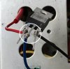
I use a wire or a pin with cross-section similar to the part leads, stick it into a vise and wind a few loops of my connecting wire around it. The result can be tightened and adjusted with small pliers or tweezers. So, it resembles wound connections on inputs/outputs of Kenwood PCBs, but in my case I apply a dab of solder when finalizing the joint. Seems to work. The little wire loops I made for connecting the triac are shown in a closeup of this photo from above [it also shows my coding system for marking out triac leads, so that I always know where each one is]:

IMG_1144_closeup.jpeg
 
Back
Top Bottom