• The move to the new server is done. There are some software and database maintenance updates in process. This has us passing the hat around to help out. We appreciate any donations. Seriously, even a dollar helps. The payment page may be found here - https://www.audiokarma.org/support.html

Fixing up and restoring a Kenwood KA-5002 integrated amplifier

Almost done!

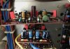
Last week, I finally managed to revisit the Main Amp PCB, plucking out two sets of old trimmers, replacing them with new Bourns trimmers and doing DC offset / bias adjustments per @eizner23 instructions (post #42 above). Here is the image of the top-down view of the Main Amp PCB with the new trimmers installed. The ones that I've chosen (from a horde of various options in Bourns catalogue) seem to fit PCB openings fairly well and could be accessed for adjustment from above with relative ease:

IMG_1149.jpeg

This makes the offset adjustments a breeze, while for bias adjustments the amp has to go on a side with belly exposed.
Checking out the old trimmers revealed that their actual values are above spec resistivities by more than 10%. Could be age-related drift or maybe they were not that accurate to start with.

Both adjustments were done successfully with the new trimmers; DC offset was reduced to ~0.1 mV, bias voltage (28.2 mV) was matched within +-0.2 mV.

After this, the amp was fully assembled and moved to my main setup for some more critical listening (see below).

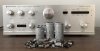
The only maintenance procedure that still remains to be done is refreshing thermal grease on the outputs. It is a mundane procedure, however, I am wondering what people use to clean off the old grease? I have a backup KA-5002 heat sink, from which I already removed the transistors and harvested their mica sheets:

IMG_1163.jpeg

As can be seen from the photo, there is plenty of ugly residue left behind, which could be pretty difficult to remove mechanically. Plus, the heat sink can be scratched in the process. Are there any other methods for removing it without sanding or scraping it off?

THX,

Wmbtn
 
Listening impressions

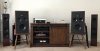
I moved the amp to my main listening room with a better CD transport and better speakers:

IMG_1159.jpeg

Tried it with both ML Motion 40 (towers in the photo, these are 4 Ohm) and Polk Monitor 10's (original, with zero upgrades). Both of these are bass reflex systems.

To my ears the amp sounds pretty good across the whole frequency range. However, I would not call it 'warm' sounding, as IMO it is more on the 'neutral' side, as probably is expected from a non-capacitor-coupled design. Low frequencies are authoritative, but well controlled and not 'muddy.' It gets pretty loud, especially on the 4 Ohm speakers, with the volume right below '4' or ~11 o'clock.

One thing that I find a bit disappointing, is that the amp is a bit restrained in 'dynamics' and does not do huge crescendo, or sound swelling. My main amp (modern, Marantz HD-AMP1) and my Sansui AU-999 are really good at this, and I did not expect KA-5002 to measure up to them. But right before bringing it in I've been using a partially recapped little AU-505 (2x 12W into 8 Ohm, recapping is NOT by me) in the same setup. That amp was equally restrained with acoustic suspension speakers, but opened up very nicely when mated with Monitor 10's. Apparently, AU-505 can do these mini-crescendos better than KA-5002, while I expected the latter to clobber the former. Or it could be that KA-5002 is not a good match for the Polks? Incidentally, my AU-505 has many other problems, like abysmal noise floor, and I will have to poke inside it in future. In comparison, KA-5002 is dead quiet, but it runs a bit hotter than the little Sansui, which is to be expected. So, this thermal grease replacement needs to happen sooner rather than later.

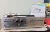
And in conclusion, here is the money shot:

IMG_1162.jpeg

The wooden side panels have been removed for now. The ones I got are pretty trashed, so their restoration may be a separate headache and I still have to think about how I want to go about it.
 
Last edited:
Also, a mild issue with operating tone controls

This is something that I confirmed during the critical listening sessions: when I turn bass/treble knobs, I sometimes hear a little 'pop' in the speakers. That happens only on the first 'click' of the knob and successive clicks are completely silent. It is also something that had not happened before I recapped the Tone Amp board.

Here I have to refer to my previous post #48: my amp had tantalum 1 uF caps in Ci1,2 positions on that board, which is different from the generic schematic. I replaced these caps with 0.47 uF Wima film following the schematic and now I wonder if that could be the source of the problem I am having now. This issue is not too annoying -- and I plan to mate this amp with an equalizer anyway -- but I will try to revisit the Tone Amp board, put 1 uF film into Ci1,2 position and report back on whether this fixes the problem. Naturally, I am pretty glad I was taking detailed notes about my recapping progress in this thread.

Wmbtn
 
I am wondering what people use to clean off the old grease?
No metal! A scrape makes for poor heat transfer. I wipe, use alcohol, the WD40 for stubborn parts, then use alcohol again.

I sometimes hear a little 'pop' in the speakers. That happens only on the first 'click' of the knob and successive clicks are completely silent.
KA-6000 and 6004 have similar set-ups. In the center position, the tone controls are fully out of the circuits and the rotary switch is not contacting any circuitry...completely defeated. When you move to the first off-center position, you engage new circuitry, thus the pop. Consider it a feature that lets you know that the tone controls are engaged.
 
No metal! A scrape makes for poor heat transfer. I wipe, use alcohol, the WD40 for stubborn parts, then use alcohol again.

Big THX for the advice! Naturally, if we scratch things, no amount of grease in between surfaces will help improve thermal flow. And this sort of heat sink is not that easy to polish out, especially when it is attached to the amp chassis. KA-400X series is simpler to handle, as the heat sink is just a plate.

KA-6000 and 6004 have similar set-ups. In the center position, the tone controls are fully out of the circuits and the rotary switch is not contacting any circuitry...completely defeated. When you move to the first off-center position, you engage new circuitry, thus the pop. Consider it a feature that lets you know that the tone controls are engaged.

So it is a feature, not a bug -- that is very good to know! Although, KA-6006 also has a 'tone mode' switch that seems to defeat things. Interesting!
 
Although, KA-6006 also has a 'tone mode' switch that seems to defeat things. Interesting!
Looking at the schematic, the 6006 has potentiometers instead of rotary switches and resistors - an interesting tidbit. 1974 is when Kenwood moved to pots on their larger amps for tone. Good to know.
 
Looking at the schematic, the 6006 has potentiometers instead of rotary switches and resistors - an interesting tidbit. 1974 is when Kenwood moved to pots on their larger amps for tone. Good to know.

Ooops! Sorry, my bad! I meant KA-6000 of course, as that is the one with the 'Tone Mode' switch.
Honestly, I tried to read the KA-5002 schematics again but gave up on these rotary switches. Have no idea how the tone circuitry is getting bypassed. Live and learn, I guess.
 
Last edited:
Cautionary note about 'floating' capacitors

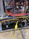
Something to keep in mind for those who'd like to use my Excel sheet information for a similar rebuild. Although I carefully measured out bigger capacitors (like axials and snap-ins), I did not do particularly well with precise matching of lead spacings and diameters of smaller ones. As a result, I got quite a few of new capacitors 'floating' over PCB surfaces instead of sitting flush with them. This image illustrates what I mean:

IMG_1035.jpeg

Also, some of capacitor replacements I chose -- due to their 'audio grade' designation or bumped up voltage rating -- were bigger than the originals, which added to the problem. Now, if anyone wants a more professional looking rebuild, with most electrolytics sitting flush with the boards (which provides somewhat better mechanical strain relief), some of my substitutions need to be reconsidered. Maybe the same specs and families could be used, but better matches in terms of size and lead spacing could be found. But in terms of electrical properties, it does not make much difference how exactly the capacitors are positioned.

I'd like to acknowledge @hopjohn for his advice in researching this issue. I also promise to do better with new builds -- got some ideas on how to estimate original capacitor sizes without sticking a caliper in, which is not always possible.

Wmbtn
 
OOH! Got the bug? Keep us posted.

Actually, always had it but until recently lacked time, space and necessary tools to follow it.
Will keep everyone posted -- my pile of Kenwood rescues is getting taller each month: KA-8300, KA-6000, KA-2600.
 
I keep listening to the recapped amp practically every day (at some reasonable but relatively loud volume) and every time it sounds a little bit better. I wonder, is that purely psychological, or am I hearing the break-in of the new capacitors in action -- same as with new speaker filters?

I also found nice wooden side panels for it (cannibalized off of rescued KA-6000 that will not be needing them for a while), so now it looks complete :D
 
I’ve never been a big believer in weeks-long burn period that would result in any memorable changes to the sound of a device. Sure, it takes some time for some devices to settle in, but it’s likely a few hours, not dove s of hours. I believe that the sound changes over time, but that it’s slow process and imperceptible to us on a day to day basis. The sound will change much more from the time you switch it on until it warms up that over the course of several months at operating temperature.

On the other hand, I have also encountered the same seeming improvement of sound over time. Because our sound memory is not that great, I put it down to the psychoacoustics of familiarity.
 
Hi there how did you bias the Kenwood KA-5002? Trying and can’t get amperage across the transistors? Am I doing something wrong here? Thanks
 
Easier and safer to measure voltage across the emitter resistor(s). Use Ohm's Law to determine the voltage required to achieve the desired bias current.

Are you sure that the amperage fuse in your meter is good?

 
Do I have to go between the 2 .047 resistors on each side? Or just the one on each side as shown
 

Attachments

  • IMG_6926.jpeg
    IMG_6926.jpeg
    173.1 KB · Views: 13
  • IMG_6927.jpeg
    IMG_6927.jpeg
    137.7 KB · Views: 14
Back
Top Bottom