

You are using an out of date browser. It may not display this or other websites correctly.
You should upgrade or use an alternative browser.
You should upgrade or use an alternative browser.
Franken VAL's
- Thread starter srbliss
- Start date

OOOH, I'm liking how this is shaping up. What is the crossover schematic, if you don't mind me asking?
Is that a 2235 woofer with 2452-SL CD's? Modern version of the 4430 I suppose.

srbliss
Active Member
That is correct.
Actually 2225H's re-coned to 2235H by a JBL guy.
Is that a 2235 woofer with 2452-SL CD's? Modern version of the 4430 I suppose.
Actually 2225H's re-coned to 2235H by a JBL guy.
srbliss
Active Member
Yes I did 16 off the 0.1Did you remove 16 turns from the 0.1 mH inductor?
'Cause otherwise, it looks correct....
7 off the 1.7 and
2 off the big 2.7.
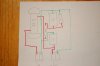
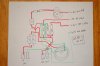
Something is wrong big time. I really think I have the L-pad wiring messed up. Should I really have both #3 terms tied together? Right now they are hooked up to the 'top' of the 15 ohm resistor.
That is the only thing not on my diagrams. I have the outputs going directly to the drivers.
Clueless right now, hope you have some incite that I am missing.
Steve

4343
Super Member
Yes I did 16 off the 0.1
7 off the 1.7 and
2 off the big 2.7.
Something is wrong big time. I really think I have the L-pad wiring messed up. Should I really have both #3 terms tied together? Right now they are hooked up to the 'top' of the 15 ohm resistor.
That is the only thing not on my diagrams. I have the outputs going directly to the drivers.
Clueless right now, hope you have some incite that I am missing.
Steve
Careful, the "big 2.7" might be lower than marked. I bought a pair of 3.3's for use in L100T>L100T3 mods, thinking to unwind to 3.2. Measurements showed that they barely measured 3.19, on one of them I had to wrap another half turn to get it that high...

Did you remove 16 turns from the 0.1 mH inductor?
'Cause otherwise, it looks correct....
Yeah, from the schematic, it looks like you should be getting sound from the horn.
And yeah, I don't think it would work without the pin 3s connected together (from the two L-pads).
Srbliss- can you post an extreme close-up of the actual crossover in question? I'm not above some wire-tracing, as long as I can actually make it out well enough for these poor old eyes to work...
Regards,
Gordon.


Is the HF driver playing at all?
Do the MF and HF controls do anything?
What you've built appears to be in compliance with my layout diagram; it's N3134, the 4430 crossover, with all of the active vs. passive switching paths bypassed into passive mode.
The 8-Ohm leg of the HF L-pad (terminals 3 and 2) with an 8-Ohm resistor in series substitutes for the 30-Ohm rheostat (R201) in the original:
http://www.jblproservice.com/pdf/Network Schematics/3134 Network.pdf
No HF output should be easy enough to trace. We'll do it here if Steve doesn't find the error today.
Don't be running that compression driver direct-connected to an amp without a protection cap in series, 10 - 50 uF.
Backstory: See my "Quick and Dirty" threads over on LHF, Zilch's Great Adventure in cloning 4430. The N3134 schematic sufficiently intimidated DIYers such that I was the only one having the requisite determination to actually build up a pair complete. That thread is linked from the Q&D index:
http://audioheritage.org/vbulletin/showthread.php?5209-4430-help!
In the course of doing that, a major endeavor, it became clear to me that 4430's unique dual-control HF topology was actually a slam-dunk easy build, once the switching stuff for active operation is removed, so I laid that out also and built up a pair to compare performance to my full-function clones and the originals. I never published the simplified design, rather, merely shared it with Duff and Steve. The reasons I didn't publish may be found via reading between the lines of Q&D -- they didn't want me doing this stuff over there. Once I figured that out, I moved here to AudioKarma and the rest is now million-view EconoWave history.
Is the HF comp in N3134 optimum for 2452H-SL on PT-F95HF? No, but it works well enough for a satisfying result, and when Duff and Steve each heard it here in ZilchLab, since I had not worked up custom comp (still haven't, actually), they said "Good 'nuff," and that's what I gave them to build. Anyone desiring to clone 4430s using the original 2344A buttcheek horn and 2426H with 2235H woofer, there it is.... :thmbsp:
http://www.audioheritage.org/vbulle...k-amp-Dirty-4430-Inspired-Contents&highlight=
Do the MF and HF controls do anything?
What you've built appears to be in compliance with my layout diagram; it's N3134, the 4430 crossover, with all of the active vs. passive switching paths bypassed into passive mode.
The 8-Ohm leg of the HF L-pad (terminals 3 and 2) with an 8-Ohm resistor in series substitutes for the 30-Ohm rheostat (R201) in the original:
http://www.jblproservice.com/pdf/Network Schematics/3134 Network.pdf
The original is a 2-terminal rheostat; the L-pad series leg plus fixed resistor substitutes for that in my design.The crossover for the JBL 4430 (which is mostly what you have here) has the high frequency lpad connections to pin 1 not pin 3, see attached. Not sure how different that is.
No HF output should be easy enough to trace. We'll do it here if Steve doesn't find the error today.
Don't be running that compression driver direct-connected to an amp without a protection cap in series, 10 - 50 uF.
Backstory: See my "Quick and Dirty" threads over on LHF, Zilch's Great Adventure in cloning 4430. The N3134 schematic sufficiently intimidated DIYers such that I was the only one having the requisite determination to actually build up a pair complete. That thread is linked from the Q&D index:
http://audioheritage.org/vbulletin/showthread.php?5209-4430-help!
In the course of doing that, a major endeavor, it became clear to me that 4430's unique dual-control HF topology was actually a slam-dunk easy build, once the switching stuff for active operation is removed, so I laid that out also and built up a pair to compare performance to my full-function clones and the originals. I never published the simplified design, rather, merely shared it with Duff and Steve. The reasons I didn't publish may be found via reading between the lines of Q&D -- they didn't want me doing this stuff over there. Once I figured that out, I moved here to AudioKarma and the rest is now million-view EconoWave history.
Is the HF comp in N3134 optimum for 2452H-SL on PT-F95HF? No, but it works well enough for a satisfying result, and when Duff and Steve each heard it here in ZilchLab, since I had not worked up custom comp (still haven't, actually), they said "Good 'nuff," and that's what I gave them to build. Anyone desiring to clone 4430s using the original 2344A buttcheek horn and 2426H with 2235H woofer, there it is.... :thmbsp:
http://www.audioheritage.org/vbulle...k-amp-Dirty-4430-Inspired-Contents&highlight=
Last edited:
O.K., start tracing using a cheap driver if you have one around, even a clock-radio speaker, as the highpass is 1 kHz. Connect your amp to the HF input, one driver lead connected to common, and use the second lead as a probe.
Start at the input, then go sequentially through the circuit, e.g., does it play with your "probe" touching the output of the dual 3uF cap pair? If so, output of the Mid L-pad center terminal?
Another good possibility is that the common connection is incomplete somewhere along its path between input and output.... :yes:
Start at the input, then go sequentially through the circuit, e.g., does it play with your "probe" touching the output of the dual 3uF cap pair? If so, output of the Mid L-pad center terminal?
Another good possibility is that the common connection is incomplete somewhere along its path between input and output.... :yes:
Last edited:
4343
Super Member
No out put from the HF driver at all. I only had the HF direct connected for a few seconds to the amp and extreme low level just to make sure it actually worked.
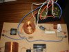
Here's how mine is layed out, hopefully you can find out what's going on.
I am just near the San Jose Flea Market, fairly close to you.
(For those that notice, the stack of resistors at the output are just standard 30 ohm, off the shelf parts, no special "Non-Inductive" here. By paralleling them, the inductance is actually less than a single 7.5 ohm.)
Attachments
Last edited:
srbliss
Active Member
Thanks for the offer
But, I built it on clear lexan and it is quite a task to trace the circuit even while holding in hands.
Steve
But, I built it on clear lexan and it is quite a task to trace the circuit even while holding in hands.
Steve
Yeah, from the schematic, it looks like you should be getting sound from the horn.
And yeah, I don't think it would work without the pin 3s connected together (from the two L-pads).
Srbliss- can you post an extreme close-up of the actual crossover in question? I'm not above some wire-tracing, as long as I can actually make it out well enough for these poor old eyes to work...
Regards,
Gordon.