• The move to the new server is done. There are some software and database maintenance updates in process. This has us passing the hat around to help out. We appreciate any donations. Seriously, even a dollar helps. The payment page may be found here - https://www.audiokarma.org/support.html

Harman Kardon A500 No Sound

mcaddie7

Active Member
Hi all!

Have a A500 that worked fine before recap, albeit one channel was much quieter than the other.

I swapped all film caps (not my first receivers, have done this many times but am always learning) and the thing still worked. I replaced the two big electrolytic and still fine.

Now onto changing the metal tube electrolytic. I swapped these out, and when I plug things in I forgot my dim bulb tester, well I hear a small hiss, a bad smell and no power tubes lighting up like normal.

I remove my caps and put it back to the original config (tube cap values were way off from original values hence the change) and no there is no sound.

It does appear that the left most (circled in red? Tubes no longer light up. So these share a common power rail or could I have burned these tubes out? I know they worked from before as the amp was working mostly.

I’m worried I killed a transformer or something. Any troubleshooting tips are welcomed.

Power tubes light up, the other three circles don’t appear to.
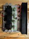
IMG_3399.jpeg


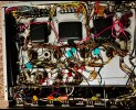
Internals, where should I be looking, dim bulb tester passes when put back to original configuration, but no sound.
IMG_3403.jpeg
IMG_3404.gif

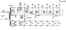
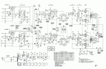
Schematic can be zoomed in.

Thanks!
 
Register to hide this ad
The front three tubes serve as a cathode resistor for the output stage, so if those are not flowing any current, the small tubes will not light.

Check the voltages in the power supply, pretty solid bet that will turn up the problem. It won't zoom enough to let me read it but its the stuff in the lower left corner, most of those points should be around the can caps in the back corner of the chassis. Start at the cardboard sleeved caps.
 
Will do! Sorry there is the link to the schematic, didn’t realize you couldn’t zoom in fully.


So these are the areas, do I just put an ohm meter on each cap point and see if I’m getting the voltage, or do I need to disconnect the transformer? I’m assuming this is in reference to ground (chassis)

IMG_3408.jpeg
IMG_3407.jpeg


For interest, these are the tubes not lighting up, the power tubes near the back are lighting but the three circles are not, and the two encircles are lighting up. Before I started this work the tubes tested good and the receiver worked, albeit a quiet channel.
IMG_3409.jpeg

Thanks for the help! I’ll measure tonight and report back
 
Are the rectifier diodes original? Those may have bought the proverbial farm.

I'd check those, to see if there's any voltage on the output going to the first filter caps.

Regards,
Gordon.
 
Are the rectifier diodes original? Those may have bought the proverbial farm.

I'd check those, to see if there's any voltage on the output going to the first filter caps.

Regards,
Gordon.
I feel a little silly asking but am always willing to learn. Whereabouts on this schematic are the rectifier diodes.
 
The noise and smell you describe is exactly what I have heard and smelled when I installed electrolytic caps backwards. Paul.
I thought the same thing, but I turned the wiring back to stock in that area, and still no sound. That coupled with I tested the new caps after this to see if they were damaged and they still have the same capacitance.
 
It sure sounds like you killed the B+. If you are not sure how to find out, it's easy.

Take a meter and set it on AC 600 volts and up.

Put the black probe on the chassis and touch the red probe to both red wires coming from tne power transformer. You should see high voltage AC on both red wires.

If you see high AC voltage, now switch your meter to DC 600 volts and up.

Put the black probe on the chassis and use the red probe to check both diodes right before the first main filter capacitor. If there is no high DC voltage here, your diodes are toast.
 
If you fried, shorted out , your PS electrolytics they are done and need to be replaced, if your tranny and rectifier diodes are still good.
 
Thank you all for the wonderful help. I’ll test how the last two responses when I get home.

The diodes appeared okay just from a ohming out test.

These are the results. I wasn’t getting the 300+ volts on the other side of this resistor, and although it should be 630, it measured 14 Mohms. I removed it from the circuit this morning and there is no continuity across the resistor, and resistance is high. Giving that there was no voltage on either side, this must be the issue right?

I think the power supplies are okay as I found all other voltages as expected
IMG_3412.png
 

Attachments

  • IMG_3412.png
    IMG_3412.png
    111.2 KB · Views: 12
yeah that should be the screen supply. No screen voltage means no current flow and no output. It explains all of the symptoms, but not the cause. Make sure there isn't a short somewhere at that node and that the cap isn't in backwards. Resistors don't just burn up for no reason.
 
So, I replaced the 680 Ohm resistor that was shorted with new power resistors. I also checked all of these resistances which all check out okay, give or take.
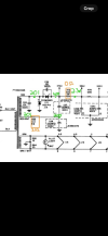
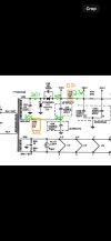
1736717776778.png

However, V1,V2,V3,V4 all still do not light up, and the amp has no sound out of it. Back to checking voltages again.
1736717854450.png

All my new caps were taken out of the circuit, and tested that none were hurt. They all have the capacitance in spec. I then rewired things back up just to double triple check according to the schematics and still these are the voltage readings.

My only hint is should the diode section be taking the 114.5V and stepping it up to 370V?

Any help sourcing some new diodes / caps (C25,C26) if you all think that is the issue?

I'm starting to loose hope on this project.
 

Attachments

  • 1736717490261.png
    1736717490261.png
    41.7 KB · Views: 4
  • 1736717580176.png
    1736717580176.png
    230.8 KB · Views: 2
Don't give up, this shouldn't involve any difficult troubleshooting. The doubler appears to be working, although all the voltages are too low. I think you need to measure the AC voltage across the output of the transformer. I would remove the load first by temporarily disconnecting one lead of both rectifiers. I believe you should measure140V - 150V AC.

Jack
 
So, I replaced the 680 Ohm resistor that was shorted with new power resistors. I also checked all of these resistances which all check out okay, give or take.
View attachment 3397959

However, V1,V2,V3,V4 all still do not light up, and the amp has no sound out of it. Back to checking voltages again.
View attachment 3397965

All my new caps were taken out of the circuit, and tested that none were hurt. They all have the capacitance in spec. I then rewired things back up just to double triple check according to the schematics and still these are the voltage readings.

My only hint is should the diode section be taking the 114.5V and stepping it up to 370V?

Any help sourcing some new diodes / caps (C25,C26) if you all think that is the issue?

I'm starting to loose hope on this project.
Going from my severely aged memory, that at times can dredge out a decent piece of information, IIRC, some of the input tubes are receiving their heater voltage from the cathodes of the 7355 tubes. Nicht vas? If those tube are not in place or if the circuit is not complete then you will not have those 3 12ax7 tubes working.
 
index.php

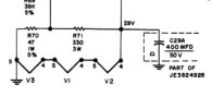
Is C25 a 10k pico-farad 1400VDC disc cap? That would equal 0.01 mfd/1400VDC.

134311-2.JPG


C26 seems to be part of a cap can (JE 3584176). :idea:

Also, V1, V2, and V3 heaters are in series. If anyone of the tube's heaters fail, they all will not light.
 
Last edited:
I'm betting you installed C29 backwards, it shorted, and burned out something in the cathode circuits of the 7355s. V1,V2, and V3's filaments are powered by the cathode current that the 7355s draw.

1736723272372.jpeg
 
None of the above suggestions (although otherwise reasonable) will pull the doubler output down a whopping 140V. Measuring +229V at the top of the doubler indicates a major failure somewhere. The doubler is functioning, because the middle connection between the caps measures +114V. I think this must either be the transformer or the 3.3Ω surge resistor.

Jack
 
There are only six passive components in the voltage doubler circuit. It’s got to be one of those components or the power transformer secondary winding. It shouldn’t be terribly difficult to track down.

As mentioned, eliminate the power transformer first by measuring the AC voltage across the secondary leads. Unloaded it should measure around 150V AC.

That being said I have seen cases where the secondary measures fine unloaded, but when under expected load, it measures much less voltage. That could be your situation here but I kinda doubt it.

If the transformer measures out fine under no load, move on to test the diodes. You can temporarily lift one leg of the ceramic caps straddling each diode. Don’t forget to test those ceramic caps as well. The ceramic caps are not strictly necessary, they keep the switching noise down but you can test the power supply without them.

Don’t make any assumptions. Test everything, but test one single thing at a time. Take notes if it helps you diagnose and keep things straight.

Don’t forget to bleed the electrolytics down between tests!
 
Back
Top Bottom