• The move to the new server is done. There are some software and database maintenance updates in process. This has us passing the hat around to help out. We appreciate any donations. Seriously, even a dollar helps. The payment page may be found here - https://www.audiokarma.org/support.html

Harman Kardon A500 No Sound

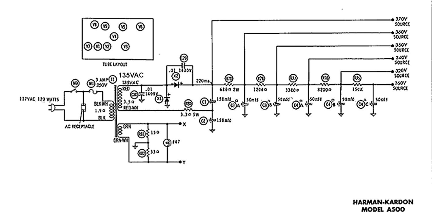
The diodes are OK, otherwise the circuit would't produce twice the voltage on the upper cap as between them. Same goes for the ceramic cap. And if any of those parts were shorted, the fuse would blow. The fuse would also blow if either doubler cap were shorted, and probably also for any internal transformer fault that could cause the voltage to be so low (such as shorted turns). R85 would cause this symptom if it has burned and the value has increased substantially.

The low doubler voltage is likely also the reason V1, V2 and V3 aren't lit and why there's no sound. V3 must be functioning in order for the amplifier to work. I'm thinking now that a simple ohmmeter test of R85 might reveal the problem. Why this resistor would burn (if that's the case) is another matter.

Jack
 
Just based on voltages across R85 it looks like the supply is pulling about 150ma. Thats not an outrageous amount, not enough to load the power supply enough to cut the output voltage nearly in half though. Also not enough to damage the resistor, its at 70mw of dissipation if those voltages are correct and the resistor is anywhere near its claimed value.

looks like 16ma between the 370 and 350v nodes, so that tells me the plates of the output tubes are running a total of 134ma. Also not insane for a set of 4 tubes, but I'd expect that at more like normal voltages.
 
Do you have a pic of your wiring after replacing C29 and C30? Seems like there must have been a faulty connection there since the cap failure happened after you replaced those. You said it worked fine after replacing the doubler caps (C27 & C28)?
 
Just based on voltages across R85 it looks like the supply is pulling about 150ma. Thats not an outrageous amount, not enough to load the power supply enough to cut the output voltage nearly in half though. Also not enough to damage the resistor, its at 70mw of dissipation if those voltages are correct and the resistor is anywhere near its claimed value.

looks like 16ma between the 370 and 350v nodes, so that tells me the plates of the output tubes are running a total of 134ma. Also not insane for a set of 4 tubes, but I'd expect that at more like normal voltages.
Okay so, currently at work but here is what I'm going to to either tonight or tomorrow for troubleshooting (thank you all so very much). Here are some thoughts after reading your comments / recap.

To start:
1) Cut wires from transformer before the doubler, as well as before R85, and check both voltages. Unloaded I'm guessing I should be measuring more?
2) I'm unfamiliar with what a doubler is. I'm guessing the zener diode / disc cap combo. It appears that it is doubling the voltage, so my guess is those 4 parts are fine. I'll still check them disconnected from the circuit and let you all know.
3) R85, the 3.3 Ohm resistor measured fine, but I replaced it anyways just clear it from my mind as an issue. The new resistor is 3.3 ohm and 5W and measured fine; I think we can eliminate this.
4) I can't test my 7355 tubes unfortunately, but they do light up and glow! But I can test the other tubes which you all are saying have heaters in series. Given that I did see smoke, could it be possible that maybe one of these blew?
5) I will check my new cap wiring for the 100th time just to be sure I'm not crazy. However at this point and given how many times I've taken it apart and put it back together I think I have it right. I'll post pictures of the wiring so you all can double check the work.

Anything I'm missing to check tonight?
 
Do you have a pic of your wiring after replacing C29 and C30? Seems like there must have been a faulty connection there since the cap failure happened after you replaced those. You said it worked fine after replacing the doubler caps (C27 & C28)?
Yes, It worked fine with all film caps replaced, I then replaced C28 and C27 and it still worked fine. I went to finish the job by replacing C29 and friends on those two can caps and all hell broke loose. lol.

Going to post pictures of my wiring tonight. I tried to keep it neat but welcome being roasted as well. Could use some comedic relief at this point.
 
It looks like you still have the original 0.05uF and 0.1uF coupling caps in the phono section too? Or is that an old photo?
 
That's an old photo. Sorry, mind circling what caps you are talking about. The two big can capacitors, I found the 400uf and one 50uf to be shorted and it was like this before I even began work. The amp made little to no sound originally so I'm guessing that's why.
It looks like you still have the original 0.05uF and 0.1uF coupling caps in the phono section too? Or is that an old photo?
 
The two big can capacitors, I found the 400uf and one 50uf to be shorted and it was like this before I even began work. The amp made little to no sound originally so I'm guessing that's why.
But you said it "worked fine before recap." Anyway, if the 3.3Ω 5W is OK, this might indeed be a transformer issue. Won't know until you take a measurement. If the 400uF cap across the three filaments was shorted, that would severely stress everything from the output tubes back to the power supply and transformer. That should have blown the fuse.

Jack
 
Okay so, currently at work but here is what I'm going to to either tonight or tomorrow for troubleshooting (thank you all so very much). Here are some thoughts after reading your comments / recap.

To start:
1) Cut wires from transformer before the doubler, as well as before R85, and check both voltages. Unloaded I'm guessing I should be measuring more?
2) I'm unfamiliar with what a doubler is. I'm guessing the zener diode / disc cap combo. It appears that it is doubling the voltage, so my guess is those 4 parts are fine. I'll still check them disconnected from the circuit and let you all know.
3) R85, the 3.3 Ohm resistor measured fine, but I replaced it anyways just clear it from my mind as an issue. The new resistor is 3.3 ohm and 5W and measured fine; I think we can eliminate this.
4) I can't test my 7355 tubes unfortunately, but they do light up and glow! But I can test the other tubes which you all are saying have heaters in series. Given that I did see smoke, could it be possible that maybe one of these blew?
5) I will check my new cap wiring for the 100th time just to be sure I'm not crazy. However at this point and given how many times I've taken it apart and put it back together I think I have it right. I'll post pictures of the wiring so you all can double check the work.

Anything I'm missing to check tonight?
Pull the output tubes and see what you get before cutting anything.


The doubler is the two diodes and the first two caps. They aren't zeners, just standard old silicon.


if you want to do some reading on it, but the junction of the two caps should be 1/2 the voltage from the top cap to the bottom cap if its working, and it looks like yours is. The circuit used in this amp is under "full wave voltage doubler" a little further down.


Are the plates on the 7355 tubes glowing? They should not be.

If the small tubes went open you'd get no current flow and high voltages everywhere.
 
You may need to test the secondary by itself, out of the rest of the circuit. To do it, you need a big wire-wound type resistor. Let's say you want to force the secondary to try to deliver 150 mA of current. At 150V secondary, with a 1k resistor connected directly across the secondary, you would need a resistor that can dissipate about 50 watts:

150 mA * 150 mA * 1k = 22.5 watts, and I'd double that wattage rating (to 50 watts) for some thermal headroom.

Setup that test using some clip leads to measure AC voltage directly across the 1k resistor. After your meter is all setup, turn the amp on so that the secondary is energized for no more than about 10 seconds. See what voltage you measure. If you measure a consistent 140V AC, the power transformer is very likely fine, and you can solder it back into the circuit and move on to looking at other issues that might be causing this. If you measure anywhere less than the 140V expected, then there's something wrong with the HV winding on the power transformer.
 
Okay so did some testing tonight.

1) The plates of the 4 output transistor are not glowing. Just the heater elements as it appears it should.
2) I used my tube tester to check for tube quality, opens and shorts and all 12AX7s passed (the ones that have zero glow to them).
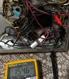
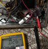
3) I then cut the two wires for each side of the secondary windings for the transformer. These are the results.
IMG_3527.jpeg
IMG_3526.jpeg
IMG_3500.jpeg

Here we can see the schematic. I cut both wires for the secondary windows. I then measured each one for AC voltage aagainst the chassis ground.

Does this mean that my transformer is bad? If so, what’s next? I have zero idea how to source a new one.


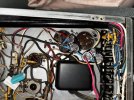
Anywho, here is my wiring as well. Please let me know if you have any suggestions to move forward. Thanks!
IMG_3517.jpeg
IMG_3518.jpeg
 

Attachments

  • IMG_3526.jpeg
    IMG_3526.jpeg
    186.9 KB · Views: 1
Pull the output tubes and see what you get before cutting anything.


The doubler is the two diodes and the first two caps. They aren't zeners, just standard old silicon.


if you want to do some reading on it, but the junction of the two caps should be 1/2 the voltage from the top cap to the bottom cap if its working, and it looks like yours is. The circuit used in this amp is under "full wave voltage doubler" a little further down.


Are the plates on the 7355 tubes glowing? They should not be.

If the small tubes went open you'd get no current flow and high voltages everywhere.
No glow on the plates. I did cut the transformer just to see (see my other reply). When I pull the 4 7355 tubes, what would you like me to measure?

Thanks for the reading! That’ll be good on my lunch break tomorrow
 
I cut both wires for the secondary windows. I then measured each one for AC voltage aagainst the chassis ground.
Using chassis ground, you're just measuring the leakage inside the transformer. This is irrelevant at this phase of troubleshooting, and the measurement number does not indicate anything amiss in that regard.

Do I understand correctly that you measured 154.6 VAC across the transformer secondary? That's about right. To have that no-load voltage available, yet only derive about 230 VDC from the doubler, indicates A) a high resistance somewhere in the supply, B) dried out (or wrong value) doubler caps, or C) an extremely heavy load (which should blow the fuse if it's the correct value). I guess the next step is to reconnect the transformer and measure doubler output voltage without a load.

Jack
 
index.php

Okay so did some testing tonight.
So your measured voltage across red and red/white is 114.5 VAC?

8cba6d9b-0bdd-4da6-b791-d4cba3748b3b.jpg

I found this schematic with the nominal secondary VAC listed. Your unit's 114.5VAC is 85% of what HK lists as nominal. Do you have a 120VAC source (the Variac is up to the full house voltage)?

What is the VAC across the green and green/white heater lines (X and Y)? It should be around 6.3 VAC (all tubes pulled). If the voltage is low too, maybe you have a tired power transformer. If the heater VAC reads 6.3VAC (+/- 5%), the problem lies in the secondary HV windings.
 
Last edited:
As stated above measure AC voltage directly across the secondary. Place one meter probe on one side of the secondary and the other meter probe on the other side of the secondary. Sounds like you did that? And you measured 154 VAC? (that would be about right, in an unloaded situation).

Do you have any big wattage handling resistors? Anywhere from 1K to 5K--just something put put a load on that secondary winding for a few seconds? I expect the secondary will deliver the current under load, but while you've got the secondary wires disconnected, might as well take a measurement with some load on the secondary. By "big wattage" resistors I mean something in the 50W territory.
 
so the reason I suggested removing the output tubes rather than unhooking the output transformers, you now have a situation where the plates have no DC voltage but the screens do. That will quickly vaporize the screens in the output tubes. Hopefully they haven't already gone, but DO NOT continue to run the amp like this. Remove the output tubes.
 
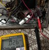
In the second pic where you're measuring 0.026 VAC, it looks like you've disconnected the red wire from the output transformer and not the red/wht wire from the PT?
 
Back
Top Bottom