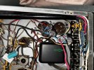
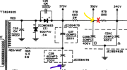
Morning all! So this thread is getting longer and it seems several people are now invested. Let me make a synopsis post along with a few next steps.
My original problem: I replaced the electrolytic caps and no longer received sound of any kind out of my amp. The 4 smaller tubes no longer lit up. There was a slight smoking smell and sizzle.
My original measurements were these directly after receiving no sound. All tubes still in the system.

Then you lovely folks came in.
Where we are at now as of this post:
* All tubes have been pulled and tested good.
* Fuse is the correct size
* All caps have been tested and have the capacitance as stated still (if you still think they could be damaged please let me know)
* I'm plugged into a 120VAC outlet.
* R85 = 3.7 Ohms (Replaced just in case)
* R78 = 665 Ohms (Replaced after finding this to be shorted, my guess is this is what sizzled).
Now, I started with measuring the
secondary windings of the transformer with 0 load. . Yellow and blue arrows will be used from here onwards to indicate my meter probes. Red X's indicate where the wires were snipped. Here I measured
155VAC.
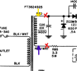
Next, I
connected the doubler circuit back up, and
disconnected the 370V tap and R78 (680Ohm). From my understanding this tests the transformer and doubler circuit without there being any other load. This measured
408 VDC. To my understanding this mostly proves that the diodes, C25-C28, and the 3.3 resistor are okay and doing their job.

I then also
measured across the Grn + Grn / WHITE windings for what I understand to be the heaters. This measured to be
6.63VAC. I understand this to mean that this part of the transformer is also functioning correctly.

Then as a suggestion from you lovely folks, I
connected back up the 370V tap, while leaving the
680 Ohm resistor cut off from the circuit. I had one probe (yellow) at the top of C27, and the other to ground (blue).
This measured 411 VDC. From my understanding, that means that this part of the circuit is working and supplying the 370V needed, thus that tap / part of the circuit isn't dragging it down.
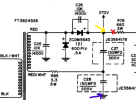
And then as a final check this AM, for BlueVUMeters, they wanted to see where the following wire was connected to. The wire in questions:

This is where that wire ends up. This I'm suspicious of as it does not quite appear to be the wiring that is in the diagram, but I also don't remember touching this as I believe this is an original wire.
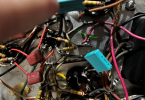

This is where I am at right now.
My next steps from your suggestions overnight are to:
* Measure the resistance of the windings between RED + RED/WHITE and GRN + GRN/WHITE just to confirm resistance of windings.
* Check the wiring in person and poke around the 340V tap and where that ends up on V5.
Any further help is greatly appreciated. I hope this update helped. If someone would like me to check further voltages, please specify what should and shouldn't be connected to the circuit. Thanks so much all!



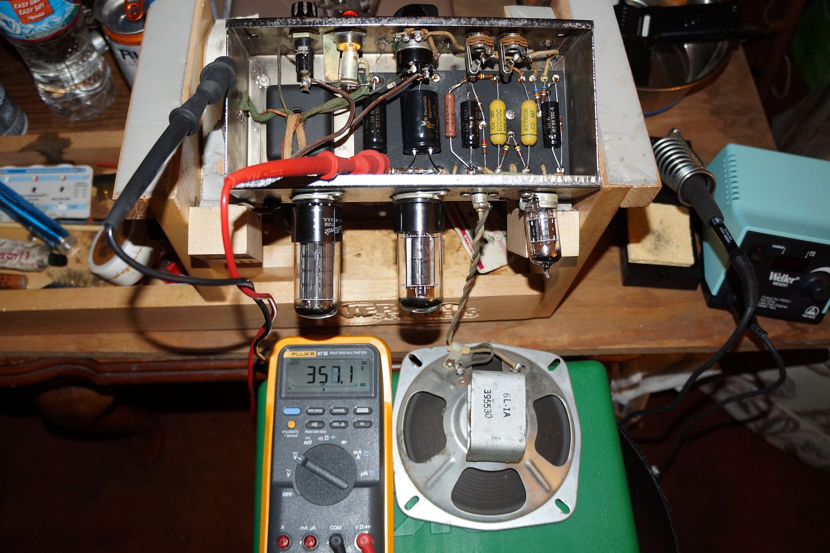

 .
.