• The move to the new server is done. There are some software and database maintenance updates in process. This has us passing the hat around to help out. We appreciate any donations. Seriously, even a dollar helps. The payment page may be found here - https://www.audiokarma.org/support.html

Harman Kardon A500 No Sound

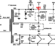
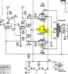
The two resistors (R29, R62) go to each plate within the 12au7 (one for each channel). I'm also curious about the black wire you have running from the 330V tap. Black is usually used for ground wiring - on my amp that lead is a dark blue wire. Just want to make sure you haven't mixed that one up with a ground connection?
I'm still at work so I'll take measurements and such tonight. However that wire looks black but is actually the blue wire you are describing, it's just covered in whatever dirt the previous owner exposed it too. The black wire, ground, goes to the ground of the caps, and then is run to the grounding bar on the chasis.

Thanks for tube explanation, I didn't realize the taps go to multiple places in the schematics. That'll help with troubleshooting.
 
Ugh, starting to really lose hope on this.

So I went home and I measured the resistance across RED + RED/WHITE and it was 3.5OhM. (Disconnected from load, yellow = red probe, blue = black probe). Is this good?
1737032888160.png


I then connected all things back up (TUBES REMOVED) and went to test each tap as was recommended.
1737033054689.png

First node measured 401V, as I looked up to change to the next node I saw plenty of smoke and the amp turned off. Checking the 3A fuse it was now blown.

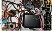
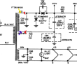
This is mostly conjecture because I had the amp on it's side, but it appeared the smoke came from this area in red.
1737033154413.png


Hopefully these tests helped you guys a little for next steps. I will buy some more 3A fuses again today. I am worried that I keep cooking something as clearly something is wrong with the circuit. I have a new cap tester coming today as well. I don't have time until Saturday AM to work on this but given all this poor amp has gone through, I'll be tested each cap, and every resistor in the amp to make sure we are still at spec from all this smoking.

-sigh- One step closer? :dunno:
 
Not being extremely familiar with these internally, is that the balance pot wired between the output tube cathodes on each channel? With no output tubes installed there shouldn't even be voltage on that pot, so if thats letting smoke out that indicates something is connected wrong.

Doubt it would be the cap, if those are the 600v (or better) parts specified, they will never be over-volted even with the tubes out. The stuff going off the edge goes to the same points in the other channel.

No chance you somehow have C29A tied to something it shouldn't be is there?

1737044100143.png


I might also suggest running the dim bulb tester for this stuff, it will limit current below the point where damage is likely to occur.
 
I might also suggest running the dim bulb tester for this stuff, it will limit current below the point where damage is likely to occur.
The solid state doubler in fact makes troubleshooting this type of problem easier, assuming a Variac is available. If the tubes are all removed, voltages can be measured with the input set to a much lower voltage. This makes it simple to find a component drawing excessive current. The dim bulb method works too, of course, and a small wattage bulb can be used if - as in this case - a short is suspected. That reminds me, it's probably time to stock up on a few values of incandescent bulbs and set them aside as test equipment. They're all being replaced with LEDs.

Jack
 
Yes I replaced all caps with slightly higher voltages just because. So that's good news!

Yes, both channels have an adjustable pot. According to the manual, you adjust them to reduce hiss in each channel and to balance them. The funny thing is, C29A actually was almost shorted with the original cap at 54pf when measured on my unit. May I ask why you suspect this cap for my own knowledge.

1737060482744.png

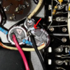
As you can see, I have the short leads and white stripes of all 3 caps wired together for ground, I believe this is correct according to the schematic. I'm going to measure all of these caps again given the latest smoke show and make sure that they are still okay capacity wise.

I thing we've eliminated the transformer now that we know the windows have a low resistance right? And given that the double, doubles the voltage, I think we know that section is good as well?

I can borrow a Variac for this weekend. How would I use that to help troubleshoot in terms of setting a voltage. I could maybe hook it up to 20VAC and then measure the nodes for you all with everything connected?
 
The solid state doubler in fact makes troubleshooting this type of problem easier, assuming a Variac is available. If the tubes are all removed, voltages can be measured with the input set to a much lower voltage. This makes it simple to find a component drawing excessive current. The dim bulb method works too, of course, and a small wattage bulb can be used if - as in this case - a short is suspected. That reminds me, it's probably time to stock up on a few values of incandescent bulbs and set them aside as test equipment. They're all being replaced with LEDs.

Jack
What voltage should I set a Variac too, and what points would you like measured once I have it set? Would you want all the taps measured again but at a lower voltage?
 
Well, you have to monitor the current if possible, but with all the tubes pulled, I would expect 30 VAC to 50 VAC to provide a good start. You need to be able to determine whether excessive current is being drawn through the 680Ω resistor. In fact, are you sure that's not what's burning? Maybe you could put your nose down close to the chassis and locate the general area by smell (power off, of course). There are a few ways to skin the cat.

Jack
 
May I ask why you suspect this cap for my own knowledge.

That cap and the balance pot should have zero volts on it with no tubes. Its not that I suspect the cap exactly, I'm wondering about the connection from that balance pot circuit. Smoke doesn't come out of circuits with no power applied, but if the wire from the balance pots was landed on a cap in the high voltage supply, or if a resistor from the high voltage supply was connected to that cap, it might explain all of this.

if the smoke came out of something else, then thats still a clue. It means something is flowing excessive current for some reason.
 
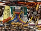
Here are a few additional pics of my amp - I just went through and replaced all the caps, the bias pots, and deleted a lot of the extraneous tone circuits. Still waiting on some nos RCA jacks and a volume pot to complete the restoration. I didn't have a 1.2K resistor on hand for R79 so that's why you see the 2 in series on that leg. I also added a 470K 2W bleed resistor at the end of the chain.

PXL_20250117_190032575.MP.jpgPXL_20250117_185952391.MP.jpgPXL_20250117_190115453.MP.jpg
 
Thank you for the pictures!

Alright, so an update for you all. I took apart the caps I had replaced. I printed out a schematic, took a highlighter, and one by one verified that all parts I had installed measured good. I then slowly placed them one by one into the circuit. Once placed, highlighted the part and path it connected to knowing it was good.

I then measured the transformer’s secondary windings again to be sure with no load; passed (154VAC, Red and Red/White).

I then measured the output of the doubler circuit right at the tip of C27 with R78 and 370V tap disconnected (no load) and this passed (412VDC).

I now hooked the amp up to a varianc. All tubes are still removed. I also placed a current measuring meter on one wire of the variac plug.
IMG_3575.jpeg

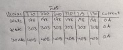
I then hooked up the circuit on the amp to be fully connected. Again, all tubes removed I measured each voltage tap in the power circuit and here are the measurements.

IMG_3576.jpeg


So I think I MAY have resolved the problem, though there is no load right now without the tubes right?

I have the same VDC across each tap for any given AC input voltage. No current was being drawn either according to the meter.

Would the next step be to put tubes in, and slowly ramp up VAC and see if there is any current draw?
 
So I became slightly impatient and due to the fact that I could measure current and slowly ramp things up in installed the tubes.

Hazah! We now have sound

I’m unsure what burnt. I did find a resistor slightly blacked so I replaced that.

One final question, channel A and B both make sound. Channel A is crisp and beautiful. Channel B is quiet and I have to turn the volume pot almost all the way up to get it to be “room volume”. Channel A is loud enough with the volume pot only midway.

Any thoughts of channel imbalance?
 
Here are a few additional pics of my amp - I just went through and replaced all the caps, the bias pots, and deleted a lot of the extraneous tone circuits. Still waiting on some nos RCA jacks and a volume pot to complete the restoration. I didn't have a 1.2K resistor on hand for R79 so that's why you see the 2 in series on that leg. I also added a 470K 2W bleed resistor at the end of the chain.

View attachment 3402215View attachment 3402216View attachment 3402217
index.php


Sir, you do excellent work on these old-school point-to-point layouts. Being super careful about the placement of the tips of the wires before soldering is 50% of the battle.
 
I have the same VDC across each tap for any given AC input voltage. No current was being drawn either according to the meter.

index.php

Are you SURE that you are measuring the correct points on the power line tree?

The cap cans have symbol marks that correspond to the nominal measuring points. Is this where you are taking those VDC measurements?

48ed0b09-98be-4dfb-9560-6de2290cf775.jpg

I put red dots for each symbol on the two cap cans.

If you are sure you are measuring correctly — you have a miswiring issue with the power supply. Visually check all the points in the PSU line, looking for wrong connections and shorts.
 
Last edited:
5301cd17-c52d-4e22-b567-99a7815f8176.jpg

They should look like this. The red DVM (VDC setting) lead to the solder tang and the black lead is secured to the chassis.
 
index.php

Are you SURE that you are measuring the correct points on the power line tree?

The cap cans have symbol marks that correspond to the nominal measuring points. Is this where you are taking those VDC measurements?

48ed0b09-98be-4dfb-9560-6de2290cf775.jpg

I put red dots for each symbol on the two cap cans.

If you are sure you are measuring correctly — you have a miswiring issue with the power supply. Visually check all the points in the PSU line, looking for wrong connections and shorts.
Wait you may have missed my previous post. The reason I was getting the same voltage at each voltage tap was because no tubes were in. I’m not sure why but a user mentioned each tap will have the same voltage with no tubes installed.

Once I installed the tubes I have the correct voltages at each tap, and I hear music now! However channel B is quiet.
 
Wait you may have missed my previous post. The reason I was getting the same voltage at each voltage tap was because no tubes were in. I’m not sure why but a user mentioned each tap will have the same voltage with no tubes installed.
No! That is not correct!

You should get near nominal voltages (especially the drop across the various tap points). They should not all be the same, tubes or no tubes. Those resistors (R78 - R82) in the lineup should be dropping the voltages, not the tubes.

What are your voltages with the tubes installed?
 
Wait you may have missed my previous post. The reason I was getting the same voltage at each voltage tap was because no tubes were in. I’m not sure why but a user mentioned each tap will have the same voltage with no tubes installed.
See post #79.
 
Once I installed the tubes I have the correct voltages at each tap, and I hear music now! However channel B is quiet.
Congrats! You’ve made it over the first hurdle.

Whatever smoked earlier might have something to do with channel B being quiet, or it might be something different.

First, get some deoxit spray. Spray it into the front panel slider switches and pots. Work those switches and pots back and forth a dozen times. See if that changes anything. The slider switches especially seem to be weak points when dust cakes in the contacts over the years.
 
Last edited:
Back
Top Bottom