• The move to the new server is done. There are some software and database maintenance updates in process. This has us passing the hat around to help out. We appreciate any donations. Seriously, even a dollar helps. The payment page may be found here - https://www.audiokarma.org/support.html

Harman Kardon A500 No Sound

As stated above measure AC voltage directly across the secondary. Place one meter probe on one side of the secondary and the other meter probe on the other side of the secondary. Sounds like you did that? And you measured 154 VAC? (that would be about right, in an unloaded situation).

Do you have any big wattage handling resistors? Anywhere from 1K to 5K--just something put put a load on that secondary winding for a few seconds? I expect the secondary will deliver the current under load, but while you've got the secondary wires disconnected, might as well take a measurement with some load on the secondary. By "big wattage" resistors I mean something in the 50W territory.
index.php


index.php


What is the 114.5 VAC then? I thought he measured 154 VAC from one secondary lead to the ground — and 0.026 VAC from the other secondary lead to the ground. Shouldn't he be measuring across the secondary output leads (red and red) and not to the ground?

I'm getting confused here. :idea: :)
 
So please bear with me as I am very new to dealing with transformers and tubes, I apologize if I've confused anyone. I admit I'm getting a bit confused now with the info being given. I'd like to start from the top, which is I'm guessing to confirm the transformer is good right? now:

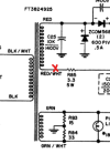
I've measured 154 VAC at this point on the transformer, with the red lead connected to the "RED" wire, and the black lead connected to chassis ground.

1736858243069.png

I then left "RED" disconnected and disconnected RED/WHT and put my red probe here, keeping my black probe on ground. This is where I essentially measured 0.026VAC. Is this good or bad?
1736858322263.png

So it seems like I may have done this wrong however?

After reading your comments, it seems like I would keep both wires disconnected still, and place a red probe on the removed RED wire and the black probe on the RED/WHT wire?

And I should remove all power tubes, or all 9 tubes all together?

Once you all get back to me on how to measure this (again, sorry I have zero idea how to mess with transfomers but am willing to learn!) I can do the same for the GRN and GRN/WHT lines just to see.
 
You have to measure across the transformer. With either end disconnected it will not give useful readings to chassis. Measure from red to red/white on the transformer. Look for AC voltage.


I'd just pull the power tubes if the leads from the output transformer are disconnected. It won't bother the other tubes to have them in place.
 
You have to measure across the transformer. With either end disconnected it will not give useful readings to chassis. Measure from red to red/white on the transformer. Look for AC voltage.


I'd just pull the power tubes if the leads from the output transformer are disconnected. It won't bother the other tubes to have them in place.
Okay thank you, I’ll do the same for green and green/white as well.

Would you like a measurement across the transformer under load as well or just disconnected?
 
You don’t need to disconnect the green and green/white wires. You can simply measure AC voltage across those two leads. I don’t believe there is reason to suspect anything wrong with the filament wiring at this point, but it’s no problem to measure it. You should read about 6.5V AC across those leads.

Yes remove power tubes for now.

Yes measure between red and red/white secondary wires. This measurement should be about 150V AC with power tubes removed.

Only if you have a big power resistor in the range of 1k to 5k at about 50 watts power handling capacity would you measure between red and Red/white under load (with that power resistor connected between red and red/white). I’m guessing you probably don’t have such a resistor handy like that if this is your first rebuild.
 
You don’t need to disconnect the green and green/white wires. You can simply measure AC voltage across those two leads. I don’t believe there is reason to suspect anything wrong with the filament wiring at this point, but it’s no problem to measure it. You should read about 6.5V AC across those leads.

Yes remove power tubes for now.

Yes measure between red and red/white secondary wires. This measurement should be about 150V AC with power tubes removed.

Only if you have a big power resistor in the range of 1k to 5k at about 50 watts power handling capacity would you measure between red and Red/white under load (with that power resistor connected between red and red/white). I’m guessing you probably don’t have such a resistor handy like that if this is your first rebuild.
Okay I’ll do this tonight thank you. For the red and red/white measurement, should that be under no load, or connected back up to the amp with the power tubes removed for measurement?

I don’t have one handy unfortunately but will definitely be buying one if you all think it’s useful to have for future rebuilds.
 
Yes under no load, meaning with red and red/white leads disconnected from circuit.

It’s always good practice to have the power tubes removed until you need them to in the circuit to test with.

I have several 50 watt power resistors handy for power supply dummy load testing. These are encased in a gold colored case with chassis mount holes molded right into the casing. I don’t use them a lot but when I do need them they are invaluable. I mounted them on a big heat sink. That helps dissipate heat somewhat but you still need to be careful when testing power supplies to not overheat them. The sizes I have are a few of each: 1k, 2k, 3k, 5k. At 50 watts each. I can connect them in series or parallel as the specific needs dictate.
 
Last edited:
I disagree with some of the advice above. it isn't necessary to load the supply with resistors to troubleshoot this. I'll just add that I own one of these amps myself, and I understand this circuit very well.

I've measured 154 VAC at this point on the transformer, with the red lead connected to the "RED" wire, and the black lead connected to chassis ground.

1736858243069.png

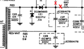
This is a valid no-load measurement. Not the way it should really be done, but you ARE measuring across the transformer secondary in this configuration through the lower doubler capacitor. The next step is to reconnect the transformer, disconnect the wires to the output transformers, disconnect the 680Ω resistor where it connects to C27 (upper doubler cap) and make another DC measurement. This will give you the unloaded DC voltage at the doubler output. If this looks OK, reconnect the wires to the output transformers and measure again. If it's still OK, then reconnect the 680Ω resistor. This can all be done with the output tubes in place. Depending on these results, you might or might not need to finally make a measurement with the output tubes removed.

Jack
 
So please bear with me as I am very new to dealing with transformers and tubes, I apologize if I've confused anyone. I admit I'm getting a bit confused now with the info being given. I'd like to start from the top, which is I'm guessing to confirm the transformer is good right?
index.php

Isn't the "114.5VAC" the measurement across the red and red/white secondary leads? Or where is this number coming from?

The schematic I posted has HK nominal at 135VAC. This, to me, is the start of the low voltage issues. :idea:

To repeat: Is the outlet voltage (are you plugged into a Variac?) — 120 VAC?
 
it isn't necessary to load the supply with resistors to troubleshoot this.
Probably true in this context. It's part of my standard testing to always test the secondary under load, but as I've said several times now, I doubt the transformer itself is the issue in this case. But I have seen situations where the transformer secondary measured fine no load but did not measure fine under load.

To the original poster: these amps sound good when working. I also have one of these amps that I refurbished it many years ago. It is worth the effort!
 
index.php

Isn't the "114.5VAC" the measurement across the red and red/white secondary leads? Or where is this number coming from?

The schematic I posted has HK nominal at 135VAC. This, to me, is the start of the low voltage issues. :idea:

To repeat: Is the outlet voltage (are you plugged into a Variac?) — 120 VAC?

Not sure what the 114.5 V means, I don't think he mentioned that measurement. It appears he disconnected the red wire from the secondary, and a red wire from the output transformer. The 154 vac measurement was taken across the secondary from the red wire to ground (since the red/wht is still connected). As Jack noted, this seems to indicate a valid no-load reading for the transformer.
 
I disagree with some of the advice above. it isn't necessary to load the supply with resistors to troubleshoot this. I'll just add that I own one of these amps myself, and I understand this circuit very well.


This is a valid no-load measurement. Not the way it should really be done, but you ARE measuring across the transformer secondary in this configuration through the lower doubler capacitor. The next step is to reconnect the transformer, disconnect the wires to the output transformers, disconnect the 680Ω resistor where it connects to C27 (upper doubler cap) and make another DC measurement. This will give you the unloaded DC voltage at the doubler output. If this looks OK, reconnect the wires to the output transformers and measure again. If it's still OK, then reconnect the 680Ω resistor. This can all be done with the output tubes in place. Depending on these results, you might or might not need to finally make a measurement with the output tubes removed.

Jack
Hopefully this isn't asking too much. When you say
The next step is to reconnect the transformer, disconnect the wires to the output transformers, disconnect the 680Ω resistor where it connects to C27 (upper doubler cap) and make another DC measurement.
I'll hook up red and red/white wires again from the transformer but am unsure where
disconnect the wires to the output transformers,
Would take place? If you could show me on the schematic that would be great.

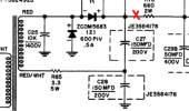
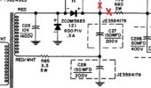
1736875240620.png
And then I'll disconnect the 680 ohm resistor here as shown. Where should the red and black probes be placed on the circuit for measurement at this point?

Thanks!
 
Not sure what the 114.5 V means, I don't think he mentioned that measurement. It appears he disconnected the red wire from the secondary, and a red wire from the output transformer. The 154 vac measurement was taken across the secondary from the red wire to ground (since the red/wht is still connected). As Jack noted, this seems to indicate a valid no-load reading for the transformer.
The 114.5 measurement is what i measured in reference to ground when the amp is on and all wires are connected. If you look at my initial post, the image shows voltages measured at each point.

Ohhhh I'll confirm when I get home but the red/white wire would be located here instead right? Feeling kinda dumb that I was measuring the wrong wire potentially. Been staring at this for too long. o_O
1736875823688.png
 
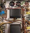
This may be a big ask but if anyone who owns this amp could post pictures of both electrolytic cap areas (I know it's a pain to open up), I'd love to compare my wiring to double triple check that the cap areas are correct as well as the transformer measurements tonight.
 
Hopefully this isn't asking too much. When you say

I'll hook up red and red/white wires again from the transformer but am unsure where

Would take place? If you could show me on the schematic that would be great.

View attachment 3399498
And then I'll disconnect the 680 ohm resistor here as shown. Where should the red and black probes be placed on the circuit for measurement at this point?

Thanks!
Disconnect at both red X's, then measure the DC voltage at the top (positive) of C27 to ground.

HK PS.jpg

Jack
 
Last edited:
Not sure what the 114.5 V means, I don't think he mentioned that measurement. It appears he disconnected the red wire from the secondary, and a red wire from the output transformer. The 154 vac measurement was taken across the secondary from the red wire to ground (since the red/wht is still connected). As Jack noted, this seems to indicate a valid no-load reading for the transformer.
He needs to read the red and red/white lines from the secondary of the power transformer in VAC.

He can measure and check other things downstream — if the secondary leads read around 135 VAC (with the amp plugged into a 120VAC outlet source). The PT must be addressed if the VAC across the two secondary lines is much less than 135 VAC (like 114.5 VAC).

If the secondary voltage is too low, every point downstream of it will read too low.

The amp must be plugged into a 120 VAC outlet. Check the Variac settings. If the source is too low, everything downstream of it will be too low.

:)
 
Last edited:
Okay team, I think this is going to be some good info for you all. Tubes are now removed for this as well. I'll wait for everyone permission to add those back in.


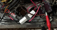
Measured across RED and RED/WHITE like you asked for the secondary windings and found 155VAC. I think the transformer is okay.
1736900589442.png
1736900644812.png


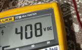
I then measured after the Doubler. and found 408 VDC. I beleive this means that the diodes, caps, and C27/C28 are healthy and doing their jobs right?
1736900681404.png
1736900700060.png

1736900715722.png


Any steps you think I should take next are greatly appreciated. I'll be cleaning up this area once I read from you all that this area is not the issue.
 
Back
Top Bottom