

You are using an out of date browser. It may not display this or other websites correctly.
You should upgrade or use an alternative browser.
You should upgrade or use an alternative browser.
Harman Kardon CD491
- Thread starter vegas79
- Start date
Checked and Reflowed all solder joints and still wont power up. Performed DBT test again and I get an orange light and then it goes out. Its as if the power supply is not connected to the rest of the unit. I have checked and rechecked all connections and can't seem to find the issue. This might be a dead horse.
Pots are all cleaned and good, On/Off power switch is cleaned and good, resoldered all joints, passes DBT but when plugged direct into wall outlet no display lights, no transport power, nothing.As Paradigm2009 posted, it sounds like the deck has poor connections-reflow solder joints and clean oxidized switches and pots.

xchg.ca
Active Member
If DBT goes on this means PSU is kicking and fuses are ok
Check this service manual
for PSU voltage points, can be on some of those wires with plugs
Check this service manual
for PSU voltage points, can be on some of those wires with plugs

Service manual for this deck is useless. I have read itIf DBT goes on this means PSU is kicking and fuses are ok
Check this service manual
for PSU voltage points, can be on some of those wires with plugs
xchg.ca
Active Member
This is for schematic not service manualService manual for this deck is useless. I have read it
On schematic you can see point where you can measure presence of +/-12, 8V etc....

genesmasher
Active Member
@taineasy - your best bet is to find someone with experience in H/K, and not mess with the top-of-the-line deck, just to gain experience. Good chance that you will make things worse, if you start pocking around randomly. CD491 service manual is actually pretty well written, and it is a relatively simple machine to work on, once you know what you are doing. Just not the deck you want to start with if the goal is to learn how to fix them.
Regarding you particular problem, as was mentioned earlier, it is likely a cam motor switch that is not working properly for some reason. Do you have power to the mecha block at all? Is the capstan motor spinning? If not, the issue is somewhere in the power supply PCB. Most frequent problem I see is old glue around the large capacitors eating off legs of diodes and transistors. You would need to pull the caps out, clean off the glue and replace corroded components to restore power to mecha. If the capstan is spinning, cam motor may have a dead spot. You could also have a physical crack in the PCB itself, severing a trace, or a cold solder joint somewhere in the circuit. Ideally, you want to take the whole board out of the deck and examine it carefully. Just take plenty of photos as you unhook all the cables, so that you know how to reconnect them. There are only four screws that hold the PS board to the chassis. Once you remove all flat cables and de-solder the three transformer leads (two orange, one black), you will be able to pull the board out.
Regarding you particular problem, as was mentioned earlier, it is likely a cam motor switch that is not working properly for some reason. Do you have power to the mecha block at all? Is the capstan motor spinning? If not, the issue is somewhere in the power supply PCB. Most frequent problem I see is old glue around the large capacitors eating off legs of diodes and transistors. You would need to pull the caps out, clean off the glue and replace corroded components to restore power to mecha. If the capstan is spinning, cam motor may have a dead spot. You could also have a physical crack in the PCB itself, severing a trace, or a cold solder joint somewhere in the circuit. Ideally, you want to take the whole board out of the deck and examine it carefully. Just take plenty of photos as you unhook all the cables, so that you know how to reconnect them. There are only four screws that hold the PS board to the chassis. Once you remove all flat cables and de-solder the three transformer leads (two orange, one black), you will be able to pull the board out.

nakmandan
Vintage Nak enthusiast
Are you 100% sure the unit was completely recapped? Or was it only a partial recap? These HK's are plagued with leaking caps on the audio board, and left long enough without corrective action, the corrosion will reach down to the board and start corroding the traces and solder pads and make repair much more difficult and labor intensive.
Your first course of action with a power problem is to check your power supply voltages. The schematic side of the fold out paper (not the connection and board layout) has all of the voltages you should be seeing. Also, there were a couple of revisions of the 491 over its production cycle, and there are two revised schematics and parts lists, 66B and 66C. Unfortunately, even though the revisions say for example "from serial number xxx on" and so forth, I have found that not always to be the case. Changes were made to earlier serial number units as well. I had to use all three service manual versions to get a complete parts list for the unit I am currently working on.
Your first course of action with a power problem is to check your power supply voltages. The schematic side of the fold out paper (not the connection and board layout) has all of the voltages you should be seeing. Also, there were a couple of revisions of the 491 over its production cycle, and there are two revised schematics and parts lists, 66B and 66C. Unfortunately, even though the revisions say for example "from serial number xxx on" and so forth, I have found that not always to be the case. Changes were made to earlier serial number units as well. I had to use all three service manual versions to get a complete parts list for the unit I am currently working on.
I greatly appreciate the comment and suggestions but after reviewing everything I have decided that repairing this may be way over my head. Without power I have no way to check the transformer or various voltages. I did find some notes written by the tech that replaced the capacitors (Yes ALL of them) Apparently we the tech received it C566 and C613 were dead short and the through board pins on diodes D08 and D09 were rotted and shorted.
genesmasher
Active Member
Yep, D8 and D9 are the ones that are buried under the largest capacitor on the PS board. They are typically covered in a thick layer of glue that's been eating them alive for 40 years. If you want help with the deck, shoot me a message. It's worth repairing.
Among the notes it says "OE D8, D9 NLA, replaced with two 1n4148 diodes in series.". Not sure what that means. Other notes mention that the "orig cust had attempted recap of PS" and made "a Frick'n mess" of the traces especially on pins of C7. "Trouble determining correct orig. trace config. Embedded and surface traces?" I may remove this board to see what he was talking about.Yep, D8 and D9 are the ones that are buried under the largest capacitor on the PS board. They are typically covered in a thick layer of glue that's been eating them alive for 40 years. If you want help with the deck, shoot me a message. It's worth repairing.
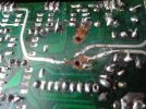
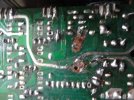
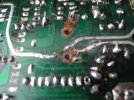
Removed the PS board to have a look at the other side. OMG what a mess. It looks like when the previous owner removed the C7 they removed a lot of trace leaving it almost unrepairable. Can't even tell what traces were connected to the negative pin.Among the notes it says "OE D8, D9 NLA, replaced with two 1n4148 diodes in series.". Not sure what that means. Other notes mention that the "orig cust had attempted recap of PS" and made "a Frick'n mess" of the traces especially on pins of C7. "Trouble determining correct orig. trace config. Embedded and surface traces?" I may remove this board to see what he was talking about.
xchg.ca
Active Member
If this is the only issue, I don't think it is a big problem. This can be rebuilt.Looks like this is officially a parts unit. Pictures tell the story
Check my vid for repairing cracked H/K 300 XM board in multiple places
I can see where the positive pin connects to two traces (I could run wire jumpers to those) but the negative pin would be a guess. The hole for the negative pin is obvious (and connects to the green trace) but there are 3 silver traces that come near the pin. I can not tell if they touch the negative pin or are just near it. It does looks like one of the silver traces touches/solders to negative pin and ends at the pin. The other two silver traces come from opposite directions and very close but appear to terminate just before the pin. Maybe all three contact the negative pin there is not enough trace to be sure. I viewed your cd491 repair video part 1 where you show that board from 53:21 to 54:56 but its still hard to see if the other silver trace (runs up-down) goes around the pin or touches the pin. One end of that silver trace travels to Q11If this is the only issue, I don't think it is a big problem. This can be rebuilt.
Check my vid for repairing cracked H/K 300 XM board in multiple places

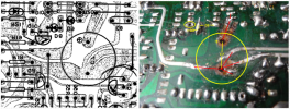
Just need to match it up with the board layout in the SM. See my example below. (need to flip the SM layout because it is viewed from the top side of the PCB.
Just put the C7 cap into holes and bend leads to secure (may want to put a dab of glue to hold it in place).
Cut short lengths of wire or left over resistor leads (red lines) and solder between broken trace and cap lead.
Missing something in yellow oval above D8??
Just put the C7 cap into holes and bend leads to secure (may want to put a dab of glue to hold it in place).
Cut short lengths of wire or left over resistor leads (red lines) and solder between broken trace and cap lead.
Missing something in yellow oval above D8??
Don't think anything is missing in hole above d8. Just one of several open/blank holes on the boardJust need to match it up with the board layout in the SM. See my example below. (need to flip the SM layout because it is viewed from the top side of the PCB.
Just put the C7 cap into holes and bend leads to secure (may want to put a dab of glue to hold it in place).
Cut short lengths of wire or left over resistor leads (red lines) and solder between broken trace and cap lead.
Missing something in yellow oval above D8??
View attachment 2995134
There are actually two leads coming off the positive pin but are very close together.Just need to match it up with the board layout in the SM. See my example below. (need to flip the SM layout because it is viewed from the top side of the PCB.
Just put the C7 cap into holes and bend leads to secure (may want to put a dab of glue to hold it in place).
Cut short lengths of wire or left over resistor leads (red lines) and solder between broken trace and cap lead.
Missing something in yellow oval above D8??
View attachment 2995134