

You are using an out of date browser. It may not display this or other websites correctly.
You should upgrade or use an alternative browser.
You should upgrade or use an alternative browser.
Harman Kardon CD491
- Thread starter vegas79
- Start date


genesmasher
Active Member
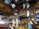
Looks like someone just yanked that cap out of the PCB, without de-soldering 
"Two 1n4148 diodes in series" means D8 and D9 were replaced with two pairs of standard 1N4148 diodes, connected head to tail. You will probably see them as these weird contraptions sticking up from the board.
"Two 1n4148 diodes in series" means D8 and D9 were replaced with two pairs of standard 1N4148 diodes, connected head to tail. You will probably see them as these weird contraptions sticking up from the board.

xchg.ca
Active Member
Looks like someone just yanked that cap out of the PCB, without de-soldering
"Two 1n4148 diodes in series" means D8 and D9 were replaced with two pairs of standard 1N4148 diodes, connected head to tail. You will probably see them as these weird contraptions sticking up from the board.
It looks to me as someone hit it first on the top, then yanked
But seriously.... I do believe this happens when ppl rock caps size to size to free it from the glue, breaking pads in same time on other side.
Last edited:
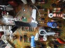
looking at diodes they do look strange. In series negative cathode to anode (black to clear) I checked on line and the originals or anything close is obsolete. Will those 1n4148 diodes that were substituted work?Looks like someone just yanked that cap out of the PCB, without de-soldering
"Two 1n4148 diodes in series" means D8 and D9 were replaced with two pairs of standard 1N4148 diodes, connected head to tail. You will probably see them as these weird contraptions sticking up from the board.
looking at diodes they do look strange. In series negative cathode to anode (black to clear) I checked on line and the originals or anything close is obsolete. Will those 1n4148 diodes that were substituted work?
Attachments
genesmasher
Active Member
Not a very neat job with those diodes (to put it mildly), but functionally correct. At least a piece of shrink tubing or some other insulation would be nice. Those long legs are flailing around, begging for a short against something nearby. Also, there may be some corrosion on the leads of the right one?

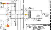
You can check your transformer voltages here (on the connector marked in yellow):
CAUTION!!! Danger of Electrical Shock. Proceed at your own risk. --- You are close to the input 120VAC on PCB-8 and fuse.
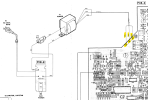
CAUTION!!! Danger of Electrical Shock. Proceed at your own risk. --- You are close to the input 120VAC on PCB-8 and fuse.
- DMM set on ACV
- Turn on Power Switch
- DMM black lead on BLK
- DMM red lead on ORG (check both ORG leads), probably should read something like 30VAC?
- Should read about 50-60VAC from ORG to ORG.
- If you get close to these voltages, transformer is OK.
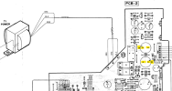
I'm only getting 16v ac Blk to either orange. That's a problem.You can check your transformer voltages here (on the connector marked in yellow):
CAUTION!!! Danger of Electrical Shock. Proceed at your own risk. --- You are close to the input 120VAC on PCB-8 and fuse.
View attachment 2998261
- DMM set on ACV
- Turn on Power Switch
- DMM black lead on BLK
- DMM red lead on ORG (check both ORG leads), probably should read something like 30VAC?
- Should read about 50-60VAC from ORG to ORG.
- If you get close to these voltages, transformer is OK.
Wonder if this unit was hit with a power surge at one time such a a lightning strikeI'm only getting 16v ac Blk to either orange. That's a problem.
Measure each cap separately. Red lead to + and Blk to - ?There are 2 main filter capacitors, C3 & C4. Can you measure the DCV from the two leads for both caps? You may need to do it from the bottom side of the board.
View attachment 2998412
View attachment 2998415
They should read about 20VDC.
C3 20V C4 NothingThere are 2 main filter capacitors, C3 & C4. Can you measure the DCV from the two leads for both caps? You may need to do it from the bottom side of the board.
View attachment 2998412
View attachment 2998415
They should read about 20VDC.
Double checked C4 is no voltage C3 is 21.5vC3 at 20VDC is OK.
Can you double check C4, it should read -20VDC (red lead to +, black to -). If you still read 0VDC then we need to check the diode bridge (D3).
CAUTION: Those fuses next to the diode rectifier are connected to the line input voltage. Do not accidentally touch with your fingers.
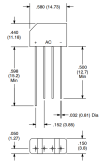
The diode rectifier D3 should look something like this, 4 pins.
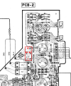
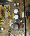
Or, maybe like this configuration in the board layout.
The diode rectifier D3 should look something like this, 4 pins.
Or, maybe like this configuration in the board layout.
- The 2 center pins should be the AC voltage coming into the rectifier from the transformer.
- The 2 outer pins are the + and - DC outputs. You might be able to get to the pins without unmounting the board.
- Set the DMM to VAC and measure from AC pin to AC pin. What do you read?
- Set the DMM to VDC and clip the black lead on the chassis. Now with the red lead check the DC at each of the outer pins, + then - (keeping the black to chassis).
- What do you read?
Last edited:
VAC from AC to AC pin 34.4vCAUTION: Those fuses next to the diode rectifier are connected to the line input voltage. Do not accidentally touch with your fingers.
The diode rectifier D3 should look something like this, 4 pins.
View attachment 2998781
Or, maybe like this configuration in the board layout.
View attachment 2998784
- The 2 center pins should be the AC voltage coming into the rectifier from the transformer.
- The 2 outer pins are the + and - DC outputs.
- Set the DMM to VAC and measure from AC pin to AC pin. What do you read?
- Set the DMM to VDC and clip the black lead on the chassis. Now with the red lead check the DC at each of the outer pins, + then - (keeping the black to chassis).
- What do you read?
VDC at + pin is 22v and at -pin 17v
genesmasher
Active Member
That's what it should be, no problem. Transformer is ok. Rectifier is unlikely to fail. Pull all plug-in flat cables off the PS PCB (take a picture before) - does it still fail DBT? If yes, start checking zeners in the power supply - D52, D4, D5, D6, D10. Also look carefully and make sure you don't have a physical short somewhere - a lead touching the ground, blob of solder over a trace, etc. Remove and inspect the four screws holding the board to chassis, wiggle the board a bit, reinstall the screws.I'm only getting 16v ac Blk to either orange. That's a problem.
Last edited: