Found a 13v zener locally and installed. Performed DBT test and still lighting up the 25w bulb but not dimming. Plugged in the wall and red "wait light comes on and goes out. The quest continuesTry your 5242b, it might be fine. If it blows up again, go with any available 14-16V zener as a replacement, like this one.


You are using an out of date browser. It may not display this or other websites correctly.
You should upgrade or use an alternative browser.
You should upgrade or use an alternative browser.
Harman Kardon CD491
- Thread starter vegas79
- Start date
It has not popped a fuse ever. Is there some sort of relay that's stuck or do I still have a short somewhere in the power supplyFound a 13v zener locally and installed. Performed DBT test and still lighting up the 25w bulb but not dimming. Plugged in the wall and red "wait light comes on and goes out. The quest continues
I think I will order the correct one. Put the new Zener 13V in. Now when performing DBT bulb is noticeably brighter but does not dim at all.
Installed new Zener but still won't power up. I did another DBT and the 25w bulb is MUCH brighter but still does not dim or go out. When plugged direct into 110 wall outlet a red/orange "wait" light comes on then goes out. Nothing after that.
Would appreciate any advice or assistanceInstalled new Zener but still won't power up. I did another DBT and the 25w bulb is MUCH brighter but still does not dim or go out. When plugged direct into 110 wall outlet a red/orange "wait" light comes on then goes out. Nothing after that.

genesmasher
Active Member
Installed new Zener but still won't power up. I did another DBT and the 25w bulb is MUCH brighter but still does not dim or go out. When plugged direct into 110 wall outlet a red/orange "wait" light comes on then goes out. Nothing after that.
What do you mean by "nothing after that"? Does the capstan spin? Does the cam motor reset after the WAIT goes out? Does the deck respond to transport commands at all? Double check you plugged in all the flat cables correctly (orientation - most likely with white wire on the left side), including two white mecha block cables on the left side of PS PCB and two flat cables that go to the buttons below.
red/orange wait light comes on for a second or two them goes dark and no power at all. No lights not button function, nothing.What do you mean by "nothing after that"? Does the capstan spin? Does the cam motor reset after the WAIT goes out? Does the deck respond to transport commands at all? Double check you plugged in all the flat cables correctly (orientation - most likely with white wire on the left side), including two white mecha block cables on the left side of PS PCB and two flat cables that go to the buttons below.
All the cables are attached properly. Once red wait light goes out there is no power to the transport or the rest of the unit.What do you mean by "nothing after that"? Does the capstan spin? Does the cam motor reset after the WAIT goes out? Does the deck respond to transport commands at all? Double check you plugged in all the flat cables correctly (orientation - most likely with white wire on the left side), including two white mecha block cables on the left side of PS PCB and two flat cables that go to the buttons below.
genesmasher
Active Member
All the cables are attached properly. Once red wait light goes out there is no power to the transport or the rest of the unit.
Look at schematic and try to figure out what else could have been affected by the D52 short. Check voltages Q1, Q2 transistors in the power supply and compare to schematic. Pull and test the other zeners I mentioned, starting with D5. Pull and check R1 and R2 fuses. Also other fuse resistors and diodes marked with a "! in triangle" in schematic (PS part). You obviously have an open resistor somewhere or another diode (or transistor) short.

From Owner's Manual:red/orange wait light comes on for a second or two them goes dark and no power at all.

What is the voltage at this point after you replaced the Zener diode?
Are you saying that the display does not light up at all. Is this on the DBT or not?

Last edited:
I had pulled and checked Q1, Q2 (checked transistors with transistor checker and they were ok) and D52 D5 D10 D4 D6 as per your instructions and only D52 was short. How do I check voltages on Q1 and Q2 while in circuit without causing a short. What are the touch points for + and - leads of multimeter? I will check R1 and R2 for continuity.Look at schematic and try to figure out what else could have been affected by the D52 short. Check voltages Q1, Q2 transistors in the power supply and compare to schematic. Pull and test the other zeners I mentioned, starting with D5. Pull and check R1 and R2 fuses. Also other fuse resistors and diodes marked with a "! in triangle" in schematic (PS part). You obviously have an open resistor somewhere or another diode (or transistor) short.
Sorry for the inconvenience but my skills are not at your level. What are the touch point for + and - leads to check the voltage in your diagram. I am concerned about touching the wrong things and causing a further issue.From Owner's Manual:
View attachment 3001363
What is the voltage at this point after you replaced the Zener diode?
Are you saying that the display does not light up at all. Is this on the DBT or not?
View attachment 3001366
@taineasy, if you don't feel confident in checking voltages with the deck powered on, don't do it.  One slip of the probe and you could short out or damage something else. Let's see if there is another way to check this.
Apparently there are 3 different versions of your deck. Can you tell me if says the model number is 66A, 66B, or 66C somewhere?
One slip of the probe and you could short out or damage something else. Let's see if there is another way to check this.Apparently there are 3 different versions of your deck. Can you tell me if says the model number is 66A, 66B, or 66C somewhere?
Last edited:
The only possible identifier I can see is that the serial number ends in a B. I once again when over the power supply and can find no shorted diodes, Zener's, Resistors or Transistors. On a DBT the bulb glows bright and immediately dims to a faint light. When I plug it into 110v the orange/red "wait" light comes on and then fades out. After that there seems to be no power to the unit other than the power supply. All the wire assemblies are plugged in correctly.@taineasy, if you don't feel confident in checking voltages with the deck powered on, don't do it.
Apparently there are 3 different versions of your deck. Can you tell me if says the model number is 66A, 66B, or 66C somewhere?
So, you are saying that none of the display lights come on, if you put a tape in the transport controls don't work (play, FF, REW), and the VU meters don't move when you play a tape?After that there seems to be no power to the unit other than the power supply.
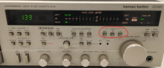
****** Check to make sure that the Timer is not set to Play or Rec.
You need to press the Off button to take it off of external timer control.
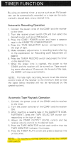
There are NO lights, NO transport functions whatsoever. It's as if the deck isSo, you are saying that none of the display lights come on, if you put a tape in the transport controls don't work (play, FF, REW), and the VU meters don't move when you play a tape?
View attachment 3001828
****** Check to make sure that the Timer is not set to Play or Rec.
You need to press the Off button to take it off of external timer control.
View attachment 3001831
turned off/powered off but in fact its ON.
genesmasher
Active Member
I had pulled and checked Q1, Q2 (checked transistors with transistor checker and they were ok) and D52 D5 D10 D4 D6 as per your instructions and only D52 was short. How do I check voltages on Q1 and Q2 while in circuit without causing a short. What are the touch points for + and - leads of multimeter? I will check R1 and R2 for continuity.
Set to multimeter to DC. Attach black lead of your multi meter to the casing of the deck or the left front screw holding down the PS board or any other ground point (usually black leads are soldered to ground). Touch each leg of each transistor separately with the red lead to measure. Be careful not to touch two legs of the transistor at the same time, or touch casing at the same time with the red lead. Push on the transistor a bit to gain better access to the legs. You don't need to take fuse resistors out for testing - just measure DC at both ends (again, black lead to the ground, use read lead to measure). If one end shows spec voltage but the other doesn't, it's open.
Set to multimeter to DC. Attach black lead of your multi meter to the casing of the deck or the left front screw holding down the PS board or any other ground point (usually black leads are soldered to ground). Touch each leg of each transistor separately with the red lead to measure. Be careful not to touch two legs of the transistor at the same time, or touch casing at the same time with the red lead. Push on the transistor a bit to gain better access to the legs. You don't need to take fuse resistors out for testing - just measure DC at both ends (again, black lead to the ground, use read lead to measure). If one end shows spec voltage but the other doesn't, it's open
Just to confirm, Touch each of the Three (3) legs (one at a time) of each transistor with the red lead with the black lead grounded to chassis and note the voltage? Should there be voltage on each of the three 3 legs?
genesmasher
Active Member
There are NO lights, NO transport functions whatsoever. It's as if the deck is
turned off/powered off but in fact its ON.
You need to measure voltages at as many transistors in the power supply as you can get and report. Use schematic as reference - all relevant voltages are listed next to each transistor. Measure voltages at both ends of R13 and R20. What is the deck's full serial number?
genesmasher
Active Member
Yes, that's the process and no, some leads will have zero voltage which is fine. Again, download relevant schematic. As dankik mentioned, there are three versions, depending on serial number.Just to confirm, Touch each of the Three (3) legs (one at a time) of each transistor with the red lead with the black lead grounded to chassis and note the voltage? Should there be voltage on each of the three 3 legs?