

You are using an out of date browser. It may not display this or other websites correctly.
You should upgrade or use an alternative browser.
You should upgrade or use an alternative browser.
Harman Kardon CD491
- Thread starter vegas79
- Start date
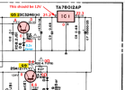
Dang it! I already placed my order from Digikey. Not sure where I will be able to find a replacement IC1 around here.R12 is good.
Based on your measurements, it looks like IC1 (12V regulator) is bad since your output pin is not 12VDC. You need to double check the voltage at Q5 collector since it cannot be 0v if pin 2 of IC1 is 21.2v?
View attachment 3003912

genesmasher
Active Member
Dang it! I already placed my order from Digikey. Not sure where I will be able to find a replacement IC1 around here.
You will probably need to place another order. I have never seen IC1 go bad. Explore the rest of the circuit first. Are the large caps still original on the power supply PCB? This is the first thing I do when I service these - replace all of these 40 year old electrolytics. There are only a dozen or so of them there, it's a $10 project that is very easy to do. At least replace all 440 uF (six of them, including C11 between IC1 and Q5), two 4500uf and the largest one (10,000uF). You can leave or replace the small ones - your choice. I usually use Nichicon UPW-series or Panasonic, Kemet, etc - anything rated for 105C and 25V or higher. While you are ordering caps, get 20 each of 10uf/25V, 22uf/25V and 1uf/50V as well - preferably audio grade, like Nichicon Fine Gold or Muse. You will need those for the main and VR boards, there is a high probability original ones all leaked (blue ones). Also pick up a dozen each of these transistors - you can sub most with these, if you discover that you have a bad one somewhere: KSC2383YTA & KSA1013YTA
This deck has already been 100% recapped with Nichicon fine gold caps prior to PS issues. What would I replace IC1 with?You will probably need to place another order. I have never seen IC1 go bad. Explore the rest of the circuit first. Are the large caps still original on the power supply PCB? This is the first thing I do when I service these - replace all of these 40 year old electrolytics. There are only a dozen or so of them there, it's a $10 project that is very easy to do. At least replace all 440 uF (six of them, including C11 between IC1 and Q5), two 4500uf and the largest one (10,000uF). You can leave or replace the small ones - your choice. I usually use Nichicon UPW-series or Panasonic, Kemet, etc - anything rated for 105C and 25V or higher. While you are ordering caps, get 20 each of 10uf/25V, 22uf/25V and 1uf/50V as well - preferably audio grade, like Nichicon Fine Gold or Muse. You will need those for the main and VR boards, there is a high probability original ones all leaked (blue ones). Also pick up a dozen each of these transistors - you can sub most with these, if you discover that you have a bad one somewhere: KSC2383YTA & KSA1013YTA
genesmasher
Active Member
Don't replace IC1 yet. We will look at it again once you have voltage on Q5.
PS. Using Fine Gold in the power supply is not ideal. FG caps are rated at 85C and 1000 hrs only, and only provide sonic benefit when used along the audio path, not in PS. I seriously doubt your main filters (4700 and 10000) are FG. Check solder joints and orientation at all capacitors - poor recapping job may explain the issues you are experiencing.
PS. Using Fine Gold in the power supply is not ideal. FG caps are rated at 85C and 1000 hrs only, and only provide sonic benefit when used along the audio path, not in PS. I seriously doubt your main filters (4700 and 10000) are FG. Check solder joints and orientation at all capacitors - poor recapping job may explain the issues you are experiencing.
I'm prepared to make one more parts order. If there is anything else (IC1 replacement?) I may need I would appreciate your input.This deck has already been 100% recapped with Nichicon fine gold caps prior to PS issues. What would I replace IC1 with?
This deck has already been 100% recapped with Nichicon fine gold caps prior to PS issues. What would I replace IC1 with?
I did not do the recap or rebuildDon't replace IC1 yet. We will look at it again once you have voltage on Q5.
PS. Using Fine Gold in the power supply is not ideal. FG caps are rated at 85C and 1000 hrs only, and only provide sonic benefit when used along the audio path, not in PS. I seriously doubt your main filters (4700 and 10000) are FG. Check solder joints and orientation at all capacitors - poor recapping job may explain the issues you are experiencing.
R12 is good.
Based on your measurements, it looks like IC1 (12V regulator) is bad since your output pin is not 12VDC. You need to double check the voltage at Q5 collector since it cannot be 0v if pin 2 of IC1 is 21.2v?
View attachment 3003912
on this. I was given to me by a friend who did not want it after it quit working. the person who recapped and replaced the belts, pinch rollers and idler charged him $400 for the repair.
I'm going to have to pull the board and somehow check Q5 from underneath at the solder connection. I has a heat sink clamped on it as tight as can be. Can't remove it without wreaking the transistor. I bent it over a bit to test but may not have had the best contact with the multimeter probe. I will have to run jumpers from the board to the transformer leads to allow me to lift it with power on.
genesmasher
Active Member
You shouldn't need to jumper the leads, they are long enough. Just remove all connectors, unscrew the board and flip it over towards the transformer. Put a towel or something insulating under it so that you don't short anything accidentally. I would go over all capacitors that were replaced and double check polarity, and check all solder joints (Q5 and big caps especially) and traces carefully. I once worked on CD391 that had a hairline crack on one side of PS PCB and several traces were broken, right next to C11, in that corner. Flex it a bit and examine the edges. The board is clearly marked for caps - circle with a filled square on the side where neg terminal should go. It doesn't matter who did the recapping - mistakes happen. Ask your friend at what point and how did the deck stop working. Symptoms may suggest the culprit. Take photos of the board on both sides and post. Finally - if you cant get to a specific contact to measure voltage, use schematic to trace down the next component in the circuit and do the measurement there. For example, collector of Q12, R13 and R28, + terminal of C11 should all have the same voltage as Q5 collector (~12V).I'm going to have to pull the board and somehow check Q5 from underneath at the solder connection. I has a heat sink clamped on it as tight as can be. Can't remove it without wreaking the transistor. I bent it over a bit to test but may not have had the best contact with the multimeter probe. I will have to run jumpers from the board to the transformer leads to allow me to lift it with power on.
Last edited:
When unplug everything except the primary wires from the transformer I am getting no DC readings at all on any transistors.You shouldn't need to jumper the leads, they are long enough. Just remove all connectors, unscrew the board and flip it over towards the transformer. Put a towel or something insulating under it so that you don't short anything accidentally. I would go over all capacitors that were replaced and double check polarity, and check all solder joints (Q5 and big caps especially) and traces carefully. I once worked on CD391 that had a hairline crack on one side of PS PCB and several traces were broken, right next to C11, in that corner. Flex it a bit and examine the edges. The board is clearly marked for caps - circle with a filled square on the side where neg terminal should go. It doesn't matter who did the recapping - mistakes happen. Ask your friend at what point and how did the deck stop working. Symptoms may suggest the culprit. Take photos of the board on both sides and post. Finally - if you cant get to a specific contact to measure voltage, use schematic to trace down the next component in the circuit and do the measurement there. For example, collector of Q12, R13 and R28, + terminal of C11 should all have the same voltage as Q5 collector (~12V).
genesmasher
Active Member
That makes no sense at all. You do get AC power at the transformer leads, right?When unplug everything except the primary wires from the transformer I am getting no DC readings at all on any transistors.
When unplug everything except the primary wires from the transformer I am getting no DC readings at all on any transistors.
Polarity on all caps is correct don't see any cracks or breaks in the traces. Checked very closely around IC1 and C11 and Q5. With all connectors unplugged I am getting NO DC readings of any kind on any transistors or IC1. You sure I should unplug all connectors?When unplug everything except the primary wires from the transformer I am getting no DC readings at all on any transistors.
black to orange 17v orange to orange 34vThat makes no sense at all. You do get AC power at the transformer leads, right?

Updated schematic with AC voltages measured. If no voltages at the transistors, then check fuses F2 and F3 (red dotted circles). Then, measure DC voltage across capacitors leads of C3 and C4. (Apologies to @genesmasher for butting in, but I had this already).
When you were measuring DCV of IC1, C11 and Q5 you did switch your meter to DCV from ACV when you measured the transformer, correct?

When you were measuring DCV of IC1, C11 and Q5 you did switch your meter to DCV from ACV when you measured the transformer, correct?
I'm starting to get overwhelmed with all of this. You are being very patient. I am an older person with some memory issues. I built and tested dozens of Heathkits back in the day but its been a while. May have to throw in the towel. Fuses have continuity. C3 and C4 measuring 23.5v DC. When measuring IC1 and Q5 I use DC with black lead to chassis correct? When measuring C11 I measure dc red to + and blk to - correct?
C11 has zero vdc across the +/- pins. Still no readings from the transistors with bk to chassis ground and using + probe to transistor legs.I'm starting to get overwhelmed with all of this. You are being very patient. I am an older person with some memory issues. I built and tested dozens of Heathkits back in the day but its been a while. May have to throw in the towel. Fuses have continuity. C3 and C4 measuring 23.5v DC. When measuring IC1 and Q5 I use DC with black lead to chassis correct? When measuring C11 I measure dc red to + and blk to - correct?
C7 has 24v across the pins.C11 has zero vdc across the +/- pins. Still no readings from the transistors with bk to chassis ground and using + probe to transistor legs.
Updated schematic with AC voltages measured. If no voltages at the transistors, then check fuses F2 and F3 (red dotted circles). Then, measure DC voltage across capacitors leads of C3 and C4. (Apologies to @genesmasher for butting in, but I had this already).
When you were measuring DCV of IC1, C11 and Q5 you did switch your meter to DCV from ACV when you measured the transformer, correct?
Let's go down the list:
- "Fuses have continuity." -- Good
- "C3 and C4 measuring 23.5v DC." -- Good
- "When measuring IC1 and Q5 I use DC with black lead to chassis correct?" -- Yes, black to chassis. Pin 1 = Input, Pin 2 = Output, Pin 3 = GND (chassis)
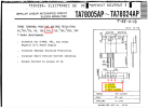
- "When measuring C11 I measure dc red to + and blk to - correct?" -- Yes, red to (+) black to (-). This should be the same as the regulator (IC1) output voltage, 12.1VDC.
- "Still no readings from the transistors with bk to chassis ground and using + probe to transistor legs." --
- Pin 2 of IC1 (previous measurement was 21V) should be the same as C11 (+) and Q5 collector?
- If not, look for a break in the PCB trace. You can turn off power and use ohms to check continuity from IC1, pin 2 (see diagram above) to C11 (+), to Q5 collector.

The higher end Harmon Kardon decks (like these) used Nakamichi transports. That transport has a tape pretension regimen. If the tape will not pretension correctly, the machine will not play. Belts fool the machine into thinking there is a tape problem.
These are real fine decks. Well into the top 10% of decks sold in the USA. IF I had one, it would get whatever it needed to keep it running right. These are not trivial machines.
I envy you'all. Been looking for a high end H-K for years. One will turn up at a yard sale some day. Meanwhile, my Denons do just fine. But you'all have some real nice stuff there
I somehow missed this thread, back when it started.
I worked at a shop that sold the CD491 and its brethren (the TD392, TD292 and such) when they were new, and actually was lucky enough to find both a TD392 and TD292 for myself.
I wish I could find a CD491 sometime.
Funny thing about these- back in the day, we actually did a three-way shootout, between a Nakamichi Dragon, a HK CD491, and a Sony TC-K500ES. We used the then-brand-new Technics SL-P1200 professional CD player as a source, through a DBX 200X tape switch box, which allowed us to record to all three decks at once, and to play back any of the three to the system. Playback was through the HK Citation 21 preamp and Citation 22 amp, through JBL 250Ti speakers (!).
All three of them were precisely adjusted for best response, in terms of head alignment and bias before recording, using reference tapes backed up by listening to the source vs. the monitored tape while trial recording.
After we had all three optimized- we recorded several tracks- including IIRC, James Newton Howard's "L'Daddy", a couple of tracks from The Doors, and a few others.
Upon playback- the remarkable result was- that the CD491 trounced both of the others. Not by a small margin. Sounded MUCH more like the original source.
To add insult to injury- I ejected the tape from the Nak, and put it into the HK- and it sounded BETTER playing back on the HK, than it did IN THE MACHINE THAT RECORDED IT. Not as good as the tape the HK recorded itself- but more dynamic and better bass.
I then tried the tape out of the HK, in the Nak- and IT SOUNDED BETTER IN THE NAK, than the tape the Nak had just made, playing back in itself. Better bass and treble and a lower noise floor.
BTW: The Sony was actually slightly better than the Nak, too. Not as dramatically better as the HK, but slightly better. Sony definitely did a good job on that one!
Regards,
Gordon.