SN 6508644BYes, that's the process and no, some leads will have zero voltage which is fine. Again, download relevant schematic. As dankik mentioned, there are three versions, depending on serial number.


You are using an out of date browser. It may not display this or other websites correctly.
You should upgrade or use an alternative browser.
You should upgrade or use an alternative browser.
Harman Kardon CD491
- Thread starter vegas79
- Start date

genesmasher
Active Member
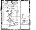
OK, you need SM revision 66B. I attached a screenshot, but you should download pdf from hifiengine ("supplement 1")SN 6508644B
Attachments
genesmasher
Active Member
This can't be right. Please note if it's positive or negative voltage when you measure. For example, Q2 should all be negative values. I will also venture a guess that you listed them in order of E-C-B (from left to right, looking at the flat side of the transistor)?WOW ready for this? Q3: 21V 7V 5V, Q4: 21V 21V 5V, Q5: 13.9V 1.7V 14.4V, Q52: 0V 21.4V 0V, Q1: 21.5V 14V 21V, Q2: 22V 13.2V 21.7V, Q9: 14V 0V 85V. ALL other transistors are a BIG FAT 0 VOLTS!.
genesmasher
Active Member
Check and/or replace R12, R13, R20, R27. Double check the orientation of D8, D9 subs. What is the voltage at cathode of D52 that you replaced? It should be near zero. Anode should be 13V.
OK I will check those.Check and/or replace R12, R13, R20, R27. Double check the orientation of D8, D9 subs. What is the voltage at cathode of D52 that you replaced? It should be near zero. Anode should be 13V.
I know the original D8 and D9's were rotted/shorted and each replaced with two 1n4148's in series. (cathode on one is connected to anode on the second such that it begins with an anode and ends with a cathode and has been installed with the cathode in the direction of the arrow on the board). Is that correct?Check and/or replace R12, R13, R20, R27. Double check the orientation of D8, D9 subs. What is the voltage at cathode of D52 that you replaced? It should be near zero. Anode should be 13V.
I see conflicting values for R20 and R13 in the service manual. One page says R13 and R20 are 10ohm and another says 4.7ohms. Don't see value of R12 or R13 listed anywhere in the parts listing. I will check buy color code.I know the original D8 and D9's were rotted/shorted and each replaced with two 1n4148's in series. (cathode on one is connected to anode on the second such that it begins with an anode and ends with a cathode and has been installed with the cathode in the direction of the arrow on the board). Is that correct?
genesmasher
Active Member
I see conflicting values for R20 and R13 in the service manual. One page says R13 and R20 are 10ohm and another says 4.7ohms. Don't see value of R12 or R13 listed anywhere in the parts listing. I will check buy color code.
Schematic has values for all parts. R1, R2 - 1 ohm 1/2w. R13 - 10 ohm 1/2 w. R20 R27 - 4.7ohm, 1/2 w. R12 is 390 ohm.
Black side of the 1N4148 pair should be on the side of the "vertical line" on the board ( |< ).

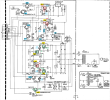
I took your voltage measurements and overlayed them on the PS schematic. The ones in green are probably OK, red are suspect, blue are not measured.
Looks like Q4 might have an emitter to collector short.
Need to double check measurements on the blue highlighted transistors.
Looks like Q4 might have an emitter to collector short.
Need to double check measurements on the blue highlighted transistors.
R13 measures 11.2 ohms, R12, R20 and R27 measure zero (0). Obviously those need replacing. Voltage at D52 (which is the one I replaced with a new 13v 500ma Zener measures zero (0) at the Anode (+) and jumps to 21 v on the cathode (-) at immediately drops to zero (0). Something wrong there. Remeasured some transistors. Q3 base is 5.1 collector is 4.9 and emitter is 20.9. Q4 base -4.9, collector is -21.8 and emitter is 20.9. Q5 ALL readings are zero(0). Q6 & Q7 ALL readings are zero(0). Q51 base13.8, collector is -1.7 and emitter is 14.5. Q1 base is 21, collector is 13.9 and emitter is 21.7. Q2 base is -21.9, collector is -13.1 and emitter is -22.5. Q9 base is 8.6, collector is 0 and emitter is .4v. Q11 all measurements are zero (0). Q902 all measurements are zero(0). IC1 base is 0, collector is 22.3 and emitter is 21.2I took your voltage measurements and overlayed them on the PS schematic. The ones in green are probably OK, red are suspect, blue are not measured.
Looks like Q4 might have an emitter to collector short.
Need to double check measurements on the blue highlighted transistors.
View attachment 3003001
That is correct.When you measure the resistor ohms, you are measuring with power off and with meter probes on both sides of the resistor correct (not to chassis ground)?
genesmasher
Active Member
With readings you are getting on IC1, the collector of Q5 can't be zero, unless there is a break in the trace or loose solder joint. Remeasure. Your multimeter lead must be in good contact. Same could be the reason for fluctuating measurement on D52. Depending on your multimeter, you may not get a reliable reading with resistors of low value. R20, R27 need to be replaced.
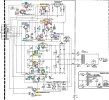
I will have to wait until Monday to check this as this is Thanksgiving weekend here and I have family over. I am assuming that I still need to replace R12, R20 and R27, which I may have to order. What about the strange readings on the D52 zener. Did it short again? If so I might as well order a couple of 14v units as the 13v I used may have been too light.Here is an updated schematic with your measured voltages.
R20 & R27 are 4.7ohm FR which means Fusible Resistor (FR), I believe.
Looks like there is an open trace between the output of IC1 pin 2 (22.3v) and Q5 collector (0v).
View attachment 3003455
What do you show the value of R12 is?I will have to wait until Monday to check this as this is Thanksgiving weekend here and I have family over. I am assuming that I still need to replace R12, R20 and R27, which I may have to order. What about the strange readings on the D52 zener. Did it short again? If so I might as well order a couple of 14v units as the 13v I used may have been too light.
394 ohmsWhat do you show the value of R12 is?
I think I previously said R12 had a zero reading. That was my error.394 ohms