• The move to the new server is done. There are some software and database maintenance updates in process. This has us passing the hat around to help out. We appreciate any donations. Seriously, even a dollar helps. The payment page may be found here - https://www.audiokarma.org/support.html

Heathkit AA-100, pretty major problems

saabracer23

AK Subscriber
Subscriber
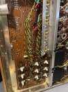
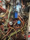
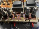
I’m going to be going through this and checking each thing, but was hoping to get ideas. I have this AA-100, it was a total basket case when I got it, and it appears to still be a basket case lol. It got a full recap, as well as all resistors. I performed all of the modifications, instructed by Gordon W. it also got all new tubes and new speaker terminals. After rebuilding it, I found that the volume pot was no longer good and a member and moderator stepped up and sent me one. It also got new RCA jacks.

IMG_1849.jpeg
IMG_1850.jpeg
IMG_1847.jpeg
IMG_1848.jpeg
IMG_1846.jpeg

One of the many issues this had when I got it was the selector switch, and the mode switch were both seized completely. I got this which is cleaned and they move easily and smoothly with new grease now.

So, onto the issues. I put the new potentiometer in and I can finally adjust the balance correctly. I powered it up and let it warm up for about 20 minutes and I got each of the output tubes set to a perfect 30 mA current. So I think you’re now was the time to listen to music on it, see how it sounds.

I went from my DAC to the auxiliary one input and one channel was very quiet while the other channel play normally, but had a loud hum. So I switched between modes and that told me that the signal for the left and right were equal, but the output was clearly not. I switch between the inputs and I was still getting a good amount of Audio coming from the speakers in all input selections, mono and stereo phono, tape, tuner, and Aux 1-2, all of the music to pass through. But the odd thing was is that the home went away on any of the other inputs, the hum only came back with it in aux 1 which is where the RCAs were plugged in.

So I thought I would try a different input, I turned off the amplifier unplugged, the RCA cables and then re-plug them into the aux 2 input. The moment I turned on the amp, it blew the main fuse. What the heck. Everything as far as the wires are connected exactly as how I found them. I am wondering if maybe the issue is the input selector switch. What would cause the main fuse to blow by having the RCA cables plugged into aux 2? I unfortunately don’t have time to look through this right now as I have to take my daughters to a birthday party, but hopefully some folks will give me ideas of what to look at in the meantime and I will check them later today. I really really appreciate any help, pretty bummed.

In order to get to the bottom of the input selector switch, I had to remove all of these trimmer plates and they solder to the boards directly below them, which is to the selector switch. I took very good photos and I’m sure I got it back together correctly, but can’t see how that would cause a fuse to blow.
IMG_1852.jpeg

Dan
 
Register to hide this ad
And of course, I should have checked it, but it had a five amp fuse in it. I’ll put a 2A SB back into it and try powering on a DBT.

Edit: thank goodness with a new 2A fuse it powers up just fine.

Dan
 
gonna offer my canned advice of breaking it into chunks. If you feed signal directly into the power amp, does it work properly with equal output and all that fun stuff?


just trying to do some basic isolation of where the problem is.

as for the blown fuse, honestly don't know but a hot restart isn't impossible. Rectifier tubes dislike that kind of thing.
 
I've rebuilt a few of these and found that the original boards seemed to have shrunk over time, the mounting holes were even off, and there were cracked tracings in numerous places. Might be something to look at.
 
gonna offer my canned advice of breaking it into chunks. If you feed signal directly into the power amp, does it work properly with equal output and all that fun stuff?


just trying to do some basic isolation of where the problem is.

as for the blown fuse, honestly don't know but a hot restart isn't impossible. Rectifier tubes dislike that kind of thing.

Luckily, it seemed like it was a hot restart I plugged the RCA’s back into aux 2 and I had no problems with power up.

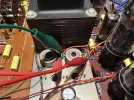
So I want to inject a signal into it, I have to have volume control of some kind so I have an Adcom preamp and I have it running through clip leads.
IMG_1853.jpeg

I don’t know if it was just a fluke that it started at the same time, but as soon as I started, turning up the volume on the preamp, my rectifier started working on the inside, pretty violently. I turned everything off and left it for four or five minutes and powered it up again with no preamp hooked up and a meter on the high-voltage. As soon as the high voltage hit about 200-250vdc it started arching on the inside again. This is a brand new gold lion, ugh! I took it out of the Heath kit and installed it into a Stromberg Carlson amp I rebuilt. It uses a 5Y3, but I don’t have anything else to test it in. I am going to measure on my Hickok though.

IMG_1856.jpeg

As soon as I powered it up, the filaments got red and then all of a sudden everything died. I found that it blew the one and a half amp fuse on the underside. I replaced the fuse and installed the 5Y3, worked great, the Sencore isolation transformer says it was drawing about 1/2 an amp. Put the GZ34 back in and it was sitting at about .25 amp, but it didn’t pull current and drop back down. It started arcing a little I side. I’m sure this brand spanking tube is toast.

Would anything I have done kill a rectifier?

Man this is becoming something.

Dan
 
I've rebuilt a few of these and found that the original boards seemed to have shrunk over time, the mounting holes were even off, and there were cracked tracings in numerous places. Might be something to look at.
I’ll take a look, thank you. Off to measure the GZ34.

Dan
 
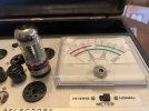
It would seem that the lion has been killed indeed.

Here is plate one
IMG_1857.jpeg

Here is plate two
IMG_1859.jpeg


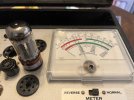
Looking at the top scale. For example, here is a fairly well used GZ34. It’s the one I actually pulled out of this AA-100.
IMG_1860.jpeg

This is quite the bummer, I have no idea what I did that would cause this. This rectifier issue did not start up until I hooked up the preamp to the amplifier input level controls. Is it possible that that could kill the rectifier? I had it running for several hours before this just letting it get nice and hot to measure voltages and such and everything looked great until I found the open potentiometer. Go through my tube stash and see if I can find some well used GZ34/5AR4s to use as sacrificial lambs. is there any potential for this to hurt the drivers, the outputs? I guess any two really they’re all expensive.

I got this tube from tonal tubes, so I’m sure it was nice and strong when it got to me. Is there any possibility that this is just randomly a tube failure? Like it was the fault of the rectifier itself?

Dan
 
Hot restarts can cause an arc and once that happens its more inclined to happen again.


I'm guessing those pots are the L and R level pots on the schematic? I was assuming a concentric volume control, not a pot like that. Problems there will cause imbalance issues, easy to ohm out though.
 
Well, I found a ruby GZ 34 which I guess could be sacrificial. I’m really hoping that hot restart was what killed the tube, I’d preferred to not have gremlins in this being easy repair. I have a whole bunch of 5Y3 and 5U4, but I know that those have different demands different filament current and voltage drop/sag. So probably best I stick with the 5AR4.
IMG_1861.jpeg

So looking at the traces on the board, you’ve got a concentric volume control, the controls both channels at once. They go from the wiper of the potentiometer and go directly to these two level input controls for the amp. So basically it’s almost like the amplifier has two volume controls that the signal has to go through. Since you had asked me to inject a signal into the amplifier just to make sure the amp is OK. I thought injecting it into that level control pot will be the best place, considering that’s the input to the amp. I guess since I have the preamp, I can go directly to the wiper of those trim pots to bypass the potentiometer altogether, but I was wanting to check those trim pots. They measure OK on a multimeter, I guess they’re weird style again. All the way at end it measures about 30 ohms and then as you turn it, it goes all the way up to about 300 kohms and then drops back about 50 ohms. So both extremes of the turn have low resistance.

About to head out, when I return, I will throw the ruby in and see how it goes.

Dan
 
Last edited:
Might be worth investing in one of these and test with a dbt.
No affiliation
You're voltages will tend to be higher. On a long term basis you can put a dropping resistor in series. For testing short term , shouldn't really hurt anything. Stops you from torching rectifier tubes if it's some other issue.
 
I have a pair of these for testing purposes. Can add a fuse to the mix as well. The ones i have aren't potted so very easy to modify. Maybe 200ma slow blow. Enough to charge the caps, but if there is a short it will open before anything ugly happens
 
I have a pair of these for testing purposes. Can add a fuse to the mix as well. The ones i have aren't potted so very easy to modify. Maybe 200ma slow blow. Enough to charge the caps, but if there is a short it will open before anything ugly happens

That is pretty smart, I should have totally done that. so instead of purchasing one I’d like to take an old broken socket and convert it. I see a few different layouts online. Which would you recommend? Do yours have a fuse built into them? Recall to have a dropping resistor as well. I know the voltage drop across that resistor is all dependent on the current being drawn, but maybe an all around. 100 ohms a “good” value?

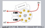
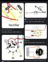
I read that 5Y3s are interchangeable with 5AR4, it’s just a lighter duty tube, but these images oddly give different pins that the diodes are soldered to.

IMG_1864.jpeg
IMG_1866.jpeg
IMG_1867.jpeg
IMG_1869.jpeg

Never trust what you see on the Internet lol

I have plenty of 1N4007, 1N5408, .01uf (only 2 kv) caps, fuses, plenty of large dropping resistors and oddly a couple of 6080s that gassed out so whatever you can point me to I’ll get it going. Looks like the 1N4007 should work, being each plate is only rated for 220 mA? Thank you so much!


Edit: I thought I should attach a photo of my particular socket.
IMG_1870.jpeg

So the filament, heater, are on pins eight and two. The AC lines going in are to pin four and six. The DC is on eight, would not have guessed that a filament line and the high voltage DC would share the same pin

So since pin five is not used, they’re very first photo is exactly like the third photo, but they’re using empty pin as a junction point for a dropping resistor, neat
Dan
 
Last edited:
Mine don't currently have fuses but I should add them. I bought them pre-made because I didn't happen to have any junk tubes I could steal an octal from, and buying the bases with the diodes already in was cheaper than buying just empty octal bases. I doubled up the diodes since it had only a single 1N4007 per side. 1kv vs the 1500v PIV rating of the tube rectifier. Now its good for 2kv. They don't get a lot of use, but they are helpful for attempting to re-form caps for initial testing since they will conduct right away instead of having to get 60v or so on the variac before the tube starts to flow.

Electrically its just a pair of diodes with the cathodes to pin 8 and one anode each to 4 and 6.

Most of the 5v rectifier tubes have the same pinout, the problem with a 5Y3 is that its only good for about half the current of a 5AR4. Just not enough for this amp. A 5U4 would do it, but 3 amp heater vs 2, not sure what the power transformer is good for but generally its not wise to assume it can handle 50% more current.

the cathode being the heater and DC out is a holdover from directly heated rectifiers. Having the heater and cathode connected takes care of any potential difference in the tube, but it does force the transformer to have the 5v winding extra insulated since its got a couple hundred volt DC riding on it. There are indirectly heated rectifiers that don't do this but you're limited on the HV to keep the tube from cooking, and some of those 6v rectifiers had problems with heater-cathode shorts and roasting transformers because of it.
 
Mine don't currently have fuses but I should add them. I bought them pre-made because I didn't happen to have any junk tubes I could steal an octal from, and buying the bases with the diodes already in was cheaper than buying just empty octal bases. I doubled up the diodes since it had only a single 1N4007 per side. 1kv vs the 1500v PIV rating of the tube rectifier. Now its good for 2kv. They don't get a lot of use, but they are helpful for attempting to re-form caps for initial testing since they will conduct right away instead of having to get 60v or so on the variac before the tube starts to flow.

Electrically its just a pair of diodes with the cathodes to pin 8 and one anode each to 4 and 6.

Most of the 5v rectifier tubes have the same pinout, the problem with a 5Y3 is that its only good for about half the current of a 5AR4. Just not enough for this amp. A 5U4 would do it, but 3 amp heater vs 2, not sure what the power transformer is good for but generally its not wise to assume it can handle 50% more current.

the cathode being the heater and DC out is a holdover from directly heated rectifiers. Having the heater and cathode connected takes care of any potential difference in the tube, but it does force the transformer to have the 5v winding extra insulated since its got a couple hundred volt DC riding on it. There are indirectly heated rectifiers that don't do this but you're limited on the HV to keep the tube from cooking, and some of those 6v rectifiers had problems with heater-cathode shorts and roasting transformers because of it.

Well, it ain’t pretty. I put a pair of 1N4007s in series on each pin as you suggested for the 2000v rating. I also included 3 33 ohm 3w resistors. I’m sure 9 W is more than fine, people are recommending a 5 W resistor, but I really wanted to use a pair of 25w 200 ohm in parallel, but it just didn’t fit. I’d like to go overkill.

IMG_1876.jpeg
IMG_1877.jpeg

Dan
 
just watch the heat output, its going to be DC current and AC ripple current. For testing this isn't super critical but just be aware of it.
 
the power dissipation in those resistors in your rectifier socket. There is DC current and AC ripple current, so the heat output will be greater than just the DC voltage drop across those resistors would imply.
 
For short term you're probably fine but I don't know that I'd be entirely comfortable running it as a forever solution. Its probably going to get plenty warm and may toast that heat shrink tubing.
 
Back
Top Bottom