• The move to the new server is done. There are some software and database maintenance updates in process. This has us passing the hat around to help out. We appreciate any donations. Seriously, even a dollar helps. The payment page may be found here - https://www.audiokarma.org/support.html

Heathkit AA-100, pretty major problems

For short term you're probably fine but I don't know that I'd be entirely comfortable running it as a forever solution. Its probably going to get plenty warm and may toast that heat shrink tubing.
This is what I came up with, a couple of 200 ohm resistors in series. They should be able to handle the heat better, now I just have to worry about the exposed voltage. I don’t know how hot this will get, but maybe like a high heat 3-D printed case or something, I don’t know probably would be best not to be in case though.
IMG_1882.jpeg
IMG_1883.jpeg

Dan
 
This is what I came up with, a couple of 200 ohm resistors in series. They should be able to handle the heat better, now I just have to worry about the exposed voltage. I don’t know how hot this will get, but maybe like a high heat 3-D printed case or something, I don’t know probably would be best not to be in case though.
View attachment 3246210
View attachment 3246211

Dan
You can coat the exposed connections/wire with liquid tape, that most Ace hardware/Home Depot stores keep in stock.
Several coats allowing the first coat to dry before applying second one, and that product comes in like 4 different colors.

I`ve had excellent success using it for over 20 yrs. and seems to hold up well in high temperature applications.
 
You can coat the exposed connections/wire with liquid tape, that most Ace hardware/Home Depot stores keep in stock.
Several coats allowing the first coat to dry before applying second one, and that product comes in like 4 different colors.

I`ve had excellent success using it for over 20 yrs. and seems to hold up well in high temperature applications.
Beautiful suggestion, thank you.

Dan
 
I had to take a small break and started on it again and thought I’d share where I’m at.

I fed a small signal into the amplifier using two seperate channels of a generator. I fed the signal through a capacitors and directly into the amplifier board, bypassing the amplifier input pots. Right channel doesn’t work. I get good output from the left, but right I’m only getting some crackling. Brand new 7199s and 7591s. I’m guessing that since I’m hearing some crackling that the output transformer is still good? I’m going to swap the tubes first off.

IMG_1960.jpeg
IMG_1959.jpeg

Dan
 
voltage checks will tell you but on the long list of things that will cause no signal to get from input to output, the output transformers are basically never at the top of my list for likely suspects. Random crackles sound like bad connections, cracked trace or bad solder would be highly likely here.
 
You are not hearing the output transformer singing are you? Like an open connection to the speaker or load? I agree, some quick continuity and/or voltage checks should help you track it down.
 
voltage checks will tell you but on the long list of things that will cause no signal to get from input to output, the output transformers are basically never at the top of my list for likely suspects. Random crackles sound like bad connections, cracked trace or bad solder would be highly likely here.

You are not hearing the output transformer singing are you? Like an open connection to the speaker or load? I agree, some quick continuity and/or voltage checks should help you track it down.

Well, luckily, it is not a transformer. I swapped the drivers and the outputs between channels and the audio output switched with them, so that told me it was one of those. I then swapped just the drivers and again the audio output swapped channels again, so that’s telling me it’s one of the drivers that is bad.

Can a tube measure quite good actually but not pass audio?

I took the suspect tube upstairs and measured it on my Hickok and it measures quite strong, both the pentode and triode sections. I took two older, weak 7199s I had and put them in and sure enough, audio in both channels.
View attachment 3255862IMG_2003.jpeg

I hope the guy that I purchased these from on eBay is cool about this. Wonder why it measures good but passes no audio.

I will wait to hear your thoughts before I reach out to the seller.

Dan
 
. Does it test obnoxiously strong? I've had that on gassy tubes which did not work right. Heater cathode short might also do it.
Not really, about the same strength as the others that I have that came with it. I measured heater to cathode and it’s nearly 2 meg which is what the others read.

Dan
 
The best tube tester is the equipment in which it’s installed. Given correct plate supply and grid bias, low cathode voltage and/or higher plate voltage indicates a weak tube.

Sometimes a tube will test fine and refuse to work in a particular circuit. Ask anyone who’s had a Hammarlund shortwave receiver with a 6C4. Even brand new NOS ones will refuse to work while well-worn oldies work fine. A mystery that’s not been solved.

When troubleshooting it’s always best to start with checking voltages. This can tell you the state of the tube, or other issues.
 
I have a couple 6P14P's that test new, but will red plate in any of my EL84 amps. All the other 6P14P's sound and work just fine. I had a 12BH7 driver test new, but would crackle intermittently. Soon after it shorted out.
So ya, they can test fine but really aren't.
 
I’ve been working on this amp periodically, I stepped away for just a little bit to give me peace of mind. It was driving me bonkers. I’ve been working on it for a little while. The first thing I addressed was the major hum when plugging in any type of source. I rewired it exactly how it was when I got it. So the person that wired it previously did have any of the. RCA sleeves grounded. I checked my photos of those RCA‘s prior to me doing any work on it and sure enough I don’t see any connection to ground. Immediately took care of the problem.

I hooked up a signal generator into an input, hooked up a pair of 8 ohm drivers, and an oscilloscope across those drivers. All pieces of test equipment I was using have isolated grounds just in case, so either battery powered or run off of a small DC power supply. Bought this oscilloscope specifically for this lol. Hooked up a CD player, and I was getting audio from both channels, but it’s still did not sound right. So I went to make adjustments on the amplifier input level adjustments.

IMG_3121.jpeg

The right channel adjustment would adjust both channels, one more than the other. The left channel adjustment would do very little to either channel. I got the two channels to be fairly even.

IMG_3122.jpeg

Here you can see me adjusting the
level adjustment, one channel would increase and decrease at a faster rate than the other.
IMG_3126.jpeg


I didn’t know what was going on, a lightbulb went off in my head. I decided to hook up only one channel input at a time. So only had an input in the right channel and then disconnected and hooked up the left channel. That’s what I found. I was getting output from both channels when only the right channel input was connected.
IMG_3130.jpeg

With the input going into the left channel was getting no output at all.

I will say that I am far more accustomed to solid state than tube and its outputs transformers, so I don’t know if this is normal or not, but doesn’t seem like it would be. Measured the resistance from the left channel 8 ohm tap to the right channel 8 ohm tap and I’m seeing a little over 1.5 ohm. So the two channel outputs are shorted together.
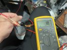
IMG_3131.jpeg

This amp is a mess. Is this reading normal? I’m just looking for pointers on where to go. One of the next things I’m going to do is insert a signal into both channels, but at different frequencies and then see if I’m getting two separate signals going to the. Level adjustment pots. If I’m getting two separate signals to that point, then I know the issue was isolated to the amplifier board. This amplifier has proved itself to be nothing but a nightmare lol. I would greatly appreciate any assistance that could be provided, so far you guys have provided much.

Thank you again,
Dan

 
The speaker to speaker thing is normal, there is a shared ground that you are reading through


Sounds like something is funky in the input wiring. Only thing i can suggest is feeding in to the left channel that doesn't work and chasing it until it goes dead. Fair bet that will be the same point that the right input is feeding into the left side.
 
The speaker to speaker thing is normal, there is a shared ground that you are reading through


Sounds like something is funky in the input wiring. Only thing i can suggest is feeding in to the left channel that doesn't work and chasing it until it goes dead. Fair bet that will be the same point that the right input is feeding into the left side.

Thanks for the comment, yeah that makes since secondaries of the two output transformers are both tied to ground. I guess I don’t really know what the DC resistance of an output secondary should be , but looks like they’re about 1 ohm each.

Dan
 
Might be worth investing in one of these and test with a dbt.
No affiliation
You're voltages will tend to be higher. On a long term basis you can put a dropping resistor in series. For testing short term , shouldn't really hurt anything. Stops you from torching rectifier tubes if it's some other issue.
Does that have inrush current limiting? You get that with a tube due to slow warm up time.
 
Back
Top Bottom