• The move to the new server is done. There are some software and database maintenance updates in process. This has us passing the hat around to help out. We appreciate any donations. Seriously, even a dollar helps. The payment page may be found here - https://www.audiokarma.org/support.html

Heathkit AA-100, pretty major problems

A lot of discussion is made about the slow warm up etc. of a 5AR4 and it is often said that you must have that. However... remember that many fisher amplifiers had silicon diodes maybe in a voltage doubler configuration. The HH Scott 340B/345/380 all had silicon diodes in the power supply. No soft start there. And early Scott equipment had a 5U4GA/GB etc. One advantage of the 5AR4 is the low voltage drop. I suspect that is more important to the engineers. However, "Your Mileage May Vary" as they say.
 
A lot of discussion is made about the slow warm up etc. of a 5AR4 and it is often said that you must have that. However... remember that many fisher amplifiers had silicon diodes maybe in a voltage doubler configuration. The HH Scott 340B/345/380 all had silicon diodes in the power supply. No soft start there. And early Scott equipment had a 5U4GA/GB etc. One advantage of the 5AR4 is the low voltage drop. I suspect that is more important to the engineers. However, "Your Mileage May Vary" as they say.
I agree.
 
Well I have some good news, it would appear that the preamp section is completely fine which is the section I was worried about the most. It’s the most difficult to work on.

I fed a signal into each channel, one channel receiving 1 kHz and the other 400 hz (common modulation frequencies, not sure why I picked those).

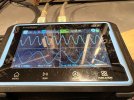
IMG_3228.jpeg
IMG_3230.jpeg

Measuring at the input of the two amplifier input level trimmers which is the two outputs of the preamp section I get two distinct signals. New to this little cheap scope so not sure how to trigger both channels running different frequencies, but…
IMG_3231.jpeg

So that leaves me with the amplifier section. Will dig in tomorrow.

Dan
 
Maybe switch the channel 1 and 2 inputs to verify if channel 2 shows the doubling, or if it stays with the 400hz channel.

I think 400 and 1k are used just because its easy to tell them apart but they aren't so different that you can't just pick a sweep time and have both show a reasonable number of cycles on the screen at the same time. They also aren't multiples of one another so no worries about harmonics causing confusion.


If you press the "funcation" button, does that book you a trip to an amusement park?


if the preamp is clean there isn't too much in the power amp that should be able to cause this. Off the top of my head i can't even think of anything likely other than maybe a wire or component touching where it shouldn't.
 
A lot of discussion is made about the slow warm up etc. of a 5AR4 and it is often said that you must have that. However... remember that many fisher amplifiers had silicon diodes maybe in a voltage doubler configuration. The HH Scott 340B/345/380 all had silicon diodes in the power supply. No soft start there. And early Scott equipment had a 5U4GA/GB etc. One advantage of the 5AR4 is the low voltage drop. I suspect that is more important to the engineers. However, "Your Mileage May Vary" as they say.

yeah I don't care much about the soft start. The caps need to be rated to deal with the higher initial voltage but thats not a big deal. The output voltage under normal load is the real issue here, and thats easy enough to fix with a suitably sized resistor. Just have to be able to shed the heat.

The other thing with the resistor, it reduces peak current in the transformer back to where it would be with a tube. Without it you'll get a little more heat, but it may or may not be enough to care about.
 
Maybe switch the channel 1 and 2 inputs to verify if channel 2 shows the doubling, or if it stays with the 400hz channel.

I think 400 and 1k are used just because its easy to tell them apart but they aren't so different that you can't just pick a sweep time and have both show a reasonable number of cycles on the screen at the same time. They also aren't multiples of one another so no worries about harmonics causing confusion.


If you press the "funcation" button, does that book you a trip to an amusement park?


if the preamp is clean there isn't too much in the power amp that should be able to cause this. Off the top of my head i can't even think of anything likely other than maybe a wire or component touching where it shouldn't.

I swapped the channel input around and measured at the same point, output of the preamp section and all looked good. The 400hz was on the opposite channel now and so was the 1 kHz signal.

I pulled the tubes in the power amp and did some work on the sockets and now for some reason the trimmers for the amp input are working fine. I think it’s because before I was feeding 1 kHz into both channels and what’s happening is they’re blending in the amp section and it was blending a level of 1 kHz into 1 kHz if that makes sense.

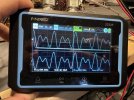
I measured at the input pins of the amplifier board. I got two distinct signals and the level trimmers adjusted them perfectly at the input of the amp board. Sorry for the glare.

So perfectly fine signal going into the amp.
IMG_3233.jpeg

Measuring at the outputs, across the speaker terminals, it’s blending the right and left channels. Or whatever this is. You can hear two tones coming from both speakers. I believe across the speakers I had changed the two input signals to 400 hz and 600 hz. I was tired of listening to the 1 kHz tone lol.

IMG_3234.jpeg

If you adjust the separation adjustment it just changes it a little.
IMG_3235.jpeg

So yeah, not sure what is causing the channels to merge like this. Hopefully it’s fairly simple.

Im too scared to push the funcation button, im not a real big fan of fun.

Dan
 
Is the speaker secondary actually grounded and not just tied channel to channel? Its got a pcb so not like you can really miswire it inside the amp circuit. Inputs and outputs are about the only possible places.

Check the feedback connection too, a swap there would do this
 
Is the speaker secondary actually grounded and not just tied channel to channel? Its got a pcb so not like you can really miswire it inside the amp circuit. Inputs and outputs are about the only possible places.

Check the feedback connection too, a swap there would do this
Measuring from the chassis to each of the speaker ground lugs I get 0.3 ohms, the secondary grounds go to those of course.

Sorry, feedback connection? I would post a photo of the schematic and ask you to point it out, but the schematic I have is pretty poor quality. Unfortunately his amplifier is a bit messy when it comes to the wiring. I’ve already found incorrect a couple of issues.

There are provisions for a center speaker. Is that wired correctly or is it shorting the two channels together?

I did check the center speaker connections, One lug is tied directly to the left channel transformer negative. The other is tied to the right channel transformer secondary 16 ohm tap (which is also tied to point “38” on the PCB) this is connected to a .02uf ceramic disc. Unfortunately, the schematic is just too hard to read to say where it goes exactly.

The center channel lug that is connected to the left channel negative, i’m not sure if the phase switch is wired correctly. When you put the phase switch to reverse it then shorts the left channel negative/center channel lug to the left channel speaker tap.

Hope this isn’t too confusing.

Dan
 

has a reasonably readable one but its not awesome. That switching crap for the speaker routing makes it kind of a mess to chase through.

but it looks like the feedback connection runs from the black output transformer lead to a 10k resistor with a 68pf across it and back to the 7199 cathode on each channel. I'm assuming it lands on an eye on the PCB but I've never had my hands in one of these. If the connection for the left and right channels were swapped you'd get a mixing like this since the feedback connection is effectively a second input that happens to be out of phase with the grid input. That would also lead to goofy cancellation of signals if they were identical.

**edit** found a better schematic

The feedback bits are on the PCB, but there is a wire from the transformer back to a terminal on the PCB. Left channel is terminal 26, right channel is 39. If those two wires got flipped for some reason it'll act stupid.
 
Last edited:

has a reasonably readable one but its not awesome. That switching crap for the speaker routing makes it kind of a mess to chase through.

but it looks like the feedback connection runs from the black output transformer lead to a 10k resistor with a 68pf across it and back to the 7199 cathode on each channel. I'm assuming it lands on an eye on the PCB but I've never had my hands in one of these. If the connection for the left and right channels were swapped you'd get a mixing like this since the feedback connection is effectively a second input that happens to be out of phase with the grid input. That would also lead to goofy cancellation of signals if they were identical.

**edit** found a better schematic

The feedback bits are on the PCB, but there is a wire from the transformer back to a terminal on the PCB. Left channel is terminal 26, right channel is 39. If those two wires got flipped for some reason it'll act stupid.

Thank you, I just checked those that the right channel negative does indeed go directly to point 39 on the board and the negative speaker post of the left channel goes to point 26 on the board, so those do appear to be correct.

I’ve gone over the phase switch and it does indeed match the schematic. I was measuring 1 ohm between the center speaker + and -, but that of course is through the transformers. Hmmmm

Dan
 
might be a little brute force but pull the 7199 from one channel and feed signal in on the other. See if you can find the signal on the complete channel showing up anywhere on the channel with the 7199 out. That would at least narrow down where its crossing over.
 
might be a little brute force but pull the 7199 from one channel and feed signal in on the other. See if you can find the signal on the complete channel showing up anywhere on the channel with the 7199 out. That would at least narrow down where its crossing over.

So sorry, don’t mean to be ignorant to this. So pull one of the 7199s say from the right channel and then feed signal into the left channel only? Then measure for output on both channels to see if there is output on both channels? I would then do the same for the other channel, pulling the 7199 from the left channel.

Are both 4 Ohm taps connected to ground? If one is floating, it will mix both both channels in that side.

I just checked and both 4 ohm taps have small leads that go directly to ground. They both measure about 0.2 ohm with the nearer lead resistance, but just to confirm it wasn’t the transformer resistance I was seeing I followed them back all the way to chassis ground.

Dan
 
Yeah, basically. If the two channels are separate at the input to the power amp and combined at the output, its got to be crossing from one to the other someplace. With one channel of the amplifier not complete, I'm thinking you'll find somewhere that the 1khz (or whatever) signal is appearing on the channel with the missing tube and that will lead to whatever the problem is.
 
Yeah, basically. If the two channels are separate at the input to the power amp and combined at the output, its got to be crossing from one to the other someplace. With one channel of the amplifier not complete, I'm thinking you'll find somewhere that the 1khz (or whatever) signal is appearing on the channel with the missing tube and that will lead to whatever the problem is.

With input into the left channel and the left channel 7199 still in place I get audio output both channels. With input into the right channel and only the right channel having a 7199 I still get audio from both channels.

If I input signal into the left channel input and have the 7199 in the right channel I still get audio from both channels, but but at a much reduced output. Same with signal into the right channel and the 7199 in the left channel.

I really hope that all makes sense.

This photo is the outputs (across speaker terminals) with signal input being the same channel that has the 7199 in it.
IMG_3423.jpeg

Dan
 
Last edited:
Ok so its coming in downstream of the 7199 stage, so definitely not a cross in the feedback circuit. Can you see audio at the grids of the channel with no 7199?
 
Ok so its coming in downstream of the 7199 stage, so definitely not a cross in the feedback circuit. Can you see audio at the grids of the channel with no 7199?

Just wanted to ask this so that I don’t accidentally damage something. Are you wanting me to check the grids if the output? Would that be pin 6? The other grid pins wouldn’t be right, 5 to ground and 4 has B+ on it.

Or check the grid of the missing 7199 socket, pin 7? Seems most of the other grid pins have voltage on them.

Thank you very much by the way, I’d be drowning without your help.

Dan
 
On my phone so i cant check the pinout but whatever the grid of the 7591 are. Should have -18 or so volts dc on it. 7591 side of the coupling caps

Just trying to figure out at what point the signal is crossing over.
 
On my phone so i cant check the pinout but whatever the grid of the 7591 are. Should have -18 or so volts dc on it. 7591 side of the coupling caps

Just trying to figure out at what point the signal is crossing over.
Okay, so yeah that would be pin 6 of the of the 7591, I’ll make sure to measure on the 7591 side of the the coupling cap.

Dan
 
Back
Top Bottom