• The move to the new server is done. There are some software and database maintenance updates in process. This has us passing the hat around to help out. We appreciate any donations. Seriously, even a dollar helps. The payment page may be found here - https://www.audiokarma.org/support.html

Heathkit AA-100, pretty major problems

I really, REALLY, hate when things like this happen. It just confuses me.

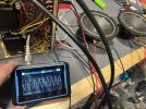
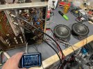
So I had one scope probe on the speaker channel that had the 7199 and the input signal and the other scope probe was on the grid of the outputs of the channel with no input and no 7199. Power it up and there is no signal on that channel, great so it’s not bleeding onto the grid. Then I notice that the speaker on that channel wasn’t playing anything, only one speaker making sound. Huh? I knew that both speakers were playing before with one of the 7199s removed.

So I shut it down, leave the 7199 removed and no signal in one of the channels and then put both scope probes on the left and right speakers. Power it up and both speakers are now playing. What the heck, is my battery operated scope causing the channels to combine? I disconnect the scope probe from the speaker that shouldn’t be playing and it’s still playing, then I disconnect the ground of the scope probe from the - terminal on the speaker and it stops playing. So the scope probe ground is causing the bleed into the other channel.

I put both 7199s in, input both channels, one 1 kHz and the other 400 hz. This time I probe one speaker at a time with only one probe. Wouldn’t you know it, one channel is outputting a perfect 1 kHz and the other 400hz.
IMG_3442.jpeg
IMG_3444.jpeg

So this entire time it was the scope ground causing all this. Has anyone seen this? I’m wondering if I had put the probe grounds directly to the chassis versus the negative terminals on the speakers if it would have prevented all of this nonsense.

The only issue now seems to be an imbalance in the channels a little bit As you turn the volume up, one channel increases with volume more than the other. Tomorrow I am going to probe around to see what might be causing that. I will start off with the volume control to see if that might be causing it.

I am going to probe the speakers again tomorrow, but try with the ground directly to the chassis to see if that works better. At least I know the two channels aren’t truly combining.

Ugh, sorry.

Dan
 
let me guess, scope ground on speaker C terminal? That would do it. This one grounds the 4 ohm terminal. The C terminal is where the negative feedback is connected so that would cause the signal to cross channel to channel.

Scope ground on 4 ohm or chassis would make it behave.

honestly didn't even think to ask how you had things connected. Normally when this happens the output is just incredibly low since its being shorted to ground through a shared signal generator and scope ground. Hadn't considered a battery powered scope doesn't have that path.
 
let me guess, scope ground on speaker C terminal? That would do it. This one grounds the 4 ohm terminal. The C terminal is where the negative feedback is connected so that would cause the signal to cross channel to channel.

Scope ground on 4 ohm or chassis would make it behave.

honestly didn't even think to ask how you had things connected. Normally when this happens the output is just incredibly low since its being shorted to ground through a shared signal generator and scope ground. Hadn't considered a battery powered scope doesn't have that path.

Well ain’t that a daisy. At least I learned something. Yes I had the scope probe across the speaker terminals like this, you know how you would normally probe any other solid state piece of equipment.
IMG_3447.jpeg

And since the negative of the speaker goes to the “C” terminal then that was causing the issues. I will connect to the four ohm lug for future testing. I’m going to be probing the the volume pot with a signal fed in to see if it behaves the same as the output. One channel is increasing at a greater volume than the other. Would love to pin that down and then this thing should be done. Then onto the matching tuner woohoo.

Dan
 
Poor volume tracking is often the control, ohm check will usually turn that one up though.

yeah there were some oddball setups with tube gear, especially early stereo stuff. The grounded 4 ohm tap thing was often used to create a center channel speaker setup. Some Fisher gear does this too, and once in a while questions come up with "it measures 1/4 watt with heavy distortion" sort of symptoms.
 
Poor volume tracking is often the control, ohm check will usually turn that one up though.

yeah there were some oddball setups with tube gear, especially early stereo stuff. The grounded 4 ohm tap thing was often used to create a center channel speaker setup. Some Fisher gear does this too, and once in a while questions come up with "it measures 1/4 watt with heavy distortion" sort of symptoms.

Well, the imbalance in the volume control while it’s still there, it was likely being exaggerated as I had, one of the speakers hooked up to the four gap while the other was hooked up to the eight tap. Oops. I got both scope probes hooked up to the eight tap and their grounds to the forum tap and I was able to measure finally.

There is still a slight imbalance, but not really enough to worry about. I have the left channel input level potentiometer all the way up and the right hand channel is about 1/4-1/3 rotation back from max. With it like this one channel is just slightly louder than the other went down low on the volume pot like maybe up to 9 o’clock. After 9 o’clock that catches up and then becomes a little bit louder than the other after say 11 o’clock. And when I say louder, I don’t mean audibly louder, I’m just measuring the voltages. I know that it’s not really measuring mV, got the scope setup wrong. But you can see in the pic that both channels say 12.50 mV each. Down lower in the volume control one will be like 6.2 mV when the other is 7 mv. After the lower channel over takes it would be something like 20 mV and the channel that caught up being 21 mV. I can live with that.

IMG_3448.jpeg

I should probably check, but I wonder if the fact that I have to have the right input pot a bit lower is because the preamp in that channels putting out a higher signal or if the right channel amplifier is amplifying it more. Hmmm

Dan
 
Well it’s definitely the one amplifier channel isn’t amplifying as much as the other. There is the two amplifier inputs being probed.

IMG_3449.jpeg

One channel is outputting nearly double the signal into the amplifier yet the output to the speakers is roughly equal. I did turn that one lower channel up to the max and both were exactly 15.62mV. So both preamp channels are perfectly matched.

Thoughts on this? Should I just leave it? Investigate? Maybe probe the grid of the outputs? That would tell me if it’s before the outputs or the outputs?

Dan
 
Last edited:
its more of a comparative measurement. It won't read on value exactly but both channels should read the same.
 
its more of a comparative measurement. It won't read on value exactly but both channels should read the same.

I will say, I've been fooled by that, a couple of times. Both in a Marantz 8B and in a Knight KB85- I had a combination of a bad cathode resistor on the output stage gain tube, AND an out of spec feedback resistor, on the same channel. If you measured resistance at the junction between them, to ground- the two channels read close to the same. But, in the case of the Marantz- the cathode resistor was too LOW in value and the feedback resistor too HIGH (causing not enough feedback/too much output level/gain), and int the case of the Knight- the OPPOSITE was happening (too HIGH value cathode resistor and too LOW feedback resistor value), causing too MUCH feedback and instability!

In both cases- I think several techs had just thrown up their hands trying to fix the amps- they had done the perfunctory measurement in-circuit- but no one before me, had actually disconnected the resistors and measured them separately. Problem solved in both cases, when proper resistors were installed!

Regards,
Gordon.
 
Check the feedback resistor for value, if thats off it has large effects on gain.

The feedback resistor will measure low, due to a shunt path - you'll need to disconnect one end to measure it.

Are we referring to R89 and R94 that come off of the black transformer tap? They’re 10k, measured in circuit they do both measure equally at 907 ohms.

I will say, I've been fooled by that, a couple of times. Both in a Marantz 8B and in a Knight KB85- I had a combination of a bad cathode resistor on the output stage gain tube, AND an out of spec feedback resistor, on the same channel. If you measured resistance at the junction between them, to ground- the two channels read close to the same. But, in the case of the Marantz- the cathode resistor was too LOW in value and the feedback resistor too HIGH (causing not enough feedback/too much output level/gain), and int the case of the Knight- the OPPOSITE was happening (too HIGH value cathode resistor and too LOW feedback resistor value), causing too MUCH feedback and instability!

In both cases- I think several techs had just thrown up their hands trying to fix the amps- they had done the perfunctory measurement in-circuit- but no one before me, had actually disconnected the resistors and measured them separately. Problem solved in both cases, when proper resistors were installed!

Regards,
Gordon.

Nice investigating and nice fix. Luckily in this case all of the resistors are brand new 1% films and they were measured before soldering them into circuit. I guess it is possible that maybe they were damaged??? I’m guessing not if they measure the same in circuit. Stars would have to align to get the same scenario you got.

Dan
 
Are we referring to R89 and R94 that come off of the black transformer tap? They’re 10k, measured in circuit they do both measure equally at 907 ohms.

yep. I didn't look at the cathode resistor value, but its 1k, 10k across 1k is basically 900 ohms so thats probably not it. Still worth confirming though. Basically what Gordon was saying about the shunt resistance skewing things enough to make it hard to be absolutely sure. With one end of the 10k lifted, the cathode resistor should read at the correct value too. Looks like R71 and R79. If either of those two are off by any significant amount it seriously affects amplifier gain.

Same if the wrong transformer tap is grounded or connected to the feedback circuit.

if that doesn't do it, the 7199 has a huge part in the total open loop gain. If thats just whipped for some reason it might do this if its tired beyond the ability of the feedback loop to correct for it. Wrong plate or screen resistors can skew the gain in that stage too. Hard to mess up the triode side but wrong parts will do it. You'd see that as very mismatched signal appearing at the grids of the 7591 tubes. If the inverter is working correctly the signal will be equal voltage but 180 out of phase. Adding the channels will give you a flat line, or very close to it.
 
Welp… again probably a learning experience. I measured at the grid of the output tubes and as I went up in volume the imbalance was there as well. I turned both of the input gains up all of the way and at that point the signal going into the grids was even through out the volume pot turn, but I still have imbalance at the speaker output so a problem with the output stage.

On a hunch I decided to remove the BDT out of the equation and go on full line voltage/current. The channel with the low output increased and now both channels are pretty much dead even throughout the turn. I figured the DBT would affect both channels equally. I guess not. I just like keeping the DBT in circuit as a just in case. I hadn’t even noticed, but as I drove it the bulbs were getting brighter and then saw a distortion in the wave form of the lower channel.

But here is the speaker outputs with both channel gains up to max.

IMG_3465.jpeg
IMG_3466.jpeg

Bummer.

Dan
 
I am wondering if the original volume pot may have been damaged by using fader lube on it. I used a no residue cleaner as well. The replacement volume pot I received seems to be working great with the exception of at about 12 o’clock there is a point that creates static in the signal. This could possibly be just some damage to the carbon track or it could be dirty. I’m really not wanting to take the chance of spraying it to dissolve the carbon track like last time. I know that there are some older pots that should not be sprayed. Are these one of them? Should I just live with it and consider it as the charm of something this old?

Dan
 
Sometimes you can disassemble a pot and reposition the wipers to one side or the other to hit some fresh carbon trace. I've only read about others doing this. Or you might find a compatible pot that you can steal the track section to install in your pot.
 
I’m not the best when it comes to follows a schematic of switches. Once switches are introduced I have trouble seeing what’s going on.

I’m going through the inputs and all looks good. I got to the tape head and immediately knew I was over driving it. On the aux and tuner input I was injecting 1v of input. For the tape I took it all the way down to 0.003v, or 3 mV. That seems very low. The sinewave didn’t clean up until I had it down to about 7-8 mV. Any above that the signal would start to distort.

IMG_3468.jpeg
IMG_3469.png
There is a bit more of a channel imbalance with the tape head input. So I’m trying yo see what portion of the circuit it has on its own before hitting the circuit the that the Aux hits. The phono section also runs very low, I have 3 mV going into it with plenty of output, but the imbalance is minimal. 3 mV seems quite low, don’t most cartridges output much more than that? Im
guessing that can be adjusted with the phono level input adjustments, I currently have them in the fully clockwise position that the manual states. Don’t want to do damage so thought I’d ask, but will turning them counter clockwise make the input less sensitive? I can’t imagine it would make it more. Does the tape input get adjusted with the phono adjustments? I don’t see anywhere it being possible to turn them down.

Thank you,
Dan
 
Last edited:
Sometimes you can disassemble a pot and reposition the wipers to one side or the other to hit some fresh carbon trace. I've only read about others doing this. Or you might find a compatible pot that you can steal the track section to install in your pot.
I think what I’m gonna do is once I get the new rectifier (coming from North Carolina, so it’s very late getting here, understandably) I’ll get my solid state rectifier out and then confirm and adjust bias on each of the outputs. I’ll then run it for a bit and work that volume control and see if I can’t work it out. It’s possible maybe that position of the pot won’t really be used.

Dan
 
Tape head input is similar to phono input, ~5mv or so. Only difference is the EQ curve. Not surprised its overdriven above 8mv.

Its not really very useful, and honestly you'd be better off modding it to be a second phono input. With more effort it could probably be another line level input but the selector switches on this thing are not really modification-friendly.

1728330665508.png

should get you a second phono input. Basically pull the two parts that make up the tape head EQ and add a jumper so the phono EQ is active in both positions.

It will also need a 47k resistor at the tape head input to get the loading right.
 
Welp… again probably a learning experience. I measured at the grid of the output tubes and as I went up in volume the imbalance was there as well. I turned both of the input gains up all of the way and at that point the signal going into the grids was even through out the volume pot turn, but I still have imbalance at the speaker output so a problem with the output stage.

On a hunch I decided to remove the BDT out of the equation and go on full line voltage/current. The channel with the low output increased and now both channels are pretty much dead even throughout the turn. I figured the DBT would affect both channels equally. I guess not. I just like keeping the DBT in circuit as a just in case. I hadn’t even noticed, but as I drove it the bulbs were getting brighter and then saw a distortion in the wave form of the lower channel.

But here is the speaker outputs with both channel gains up to max.

View attachment 3314111
View attachment 3314112

Bummer.

Dan

That can definitely happen, readily.

One of the 7199s or the output tubes, may have more of what's called "filament sensitivity" than the other. That means, that it takes more heater voltage, for the "sensitive" tube to come up to full conduction.

That can be a sign of a "tired" or defective tube- in fact, if the heater voltage cannot be turned down to 90% of normal heater voltage, without the tube starting to drop in output- that's a sign that the tube doesn't have much life left.

Regards,
Gordon.
 
Back
Top Bottom