• The move to the new server is done. There are some software and database maintenance updates in process. This has us passing the hat around to help out. We appreciate any donations. Seriously, even a dollar helps. The payment page may be found here - https://www.audiokarma.org/support.html

sae-7125

Super Member
posting some basic notes and measurements (photo journal) for an ongoing project that will eventually have "edited highlights" posted in the season-2 bench thread (also ongoing) since season-1 has reached q&a mode.

starting with a somewhat minimal familiarity in regards to "foundation era" tube audio (1940s and 1950s before stereo was invented) and its brands. so some informative backstory will help which can be located on other threads like:


highly informative although a wall of words which tends to be a migraine for some of us. screen-shot highlights from various sources will be posted and the source links as always (as is proper, cite your sources).

some familiarity developed with h.h. scott type 280 mono amp and hk citation 2 stereo amp from season-1 but this thread is heathkit territory.
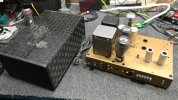
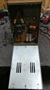
heathkit w5m - 1.jpg
mono amp 1 of 2, mains txf missing due to close encounter needed with heyboer txf repair facility

*almost within walking distance for some of us
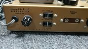


heathkit w5m - 2.jpg
closer look at brand and model, plus the nice chassis color providing good contrast for black text.

 
Register to hide this ad
this was to be a simple re-cap since the amp desperately needs it but... there are several design issues to contend with as well.

plus the current owner (local chief vinyl addict supreme, owns and operates a vinyl shop) would like improved longevity without too much sonic sacrifice. since a thd meter is not readily accessible, high accuracy adjustment will not be possible i.e. 0.0000001% thd+n at 1.21gw output (whats a jiga watt, marty mcfly) type of thing.

 
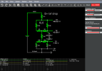
will most likely share some circuit sim designs (falstad, not precise but usable) that might cause real engineers to scream at their screen (territory of: whiskey tango foxtrot), viewer discretion is advised.

Screenshot 2026-06-20 at 20-08-05 480v 6L6 bias factory.txt - Circuit Simulator.png
* txt file attached for public learning +/- amusement. hover over resistors and use mouse-wheel to explore other values.

**menu > options > conventional current motion = deselected

expect lots of photos as usual, cause i aint typing too much.

simple equation: typing + crap eyesight = (headache / annoyance) ^ proofreading-everything * pi ^ pi.

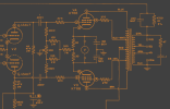
Screenshot 2026-06-20 at 20-10-22 Assembling and Using Your Heathkit High Fidelity Amplifier M...png
case in point, regarding typing

"shift" key sold separately. perhaps using / and \ as sentence start and stop vs upper case and a hard to see dot. hmm, have to think about that. could also get rid of space or double space between sentences as well...
 

Attachments

another word of caution, not everybody has the same (re)design specification preferences. some of us would like to repair once and then never see the successful system ever again (on the bench). outbox gear with a renewed timeline of 10-30 years of service. barring any act of oops (hands off the heineken, austin powers) or bolt of lightning trying to shack up with a local substation.

so some of the redesign choices are to preserver the weakest link(s), in this case one of them being the output transformer (out-txf, opt, output iron, rusted electron clatter converter) which is the 16309 for these re/re/re/re amps. details about the out-txf limits can be found in the "untapped potential" link mentioned above (20w max involving low/bass frequency, on/off txf injury +/- self-destruction).

repair / renovate / redesign / rebuild
 
*out-txf basic info


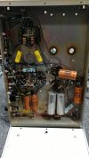
heathkit w5m - 3.jpg
looking inside amp 1 of 2, and showing how bad lighting/camera settings = bad photo

heathkit w5m - 4.jpg
carbon comp resistors and electrolytics need to go away. yellow films on either side of balance pot obviously newer (someone else was in here). also found unsoldered original connections, yeah i feel safe...

heathkit w5m - 5.jpg
out-txf beauty shot
 
:lurk:
Finished two frame up W-5M rebuilds this spring, will be interesting to see what you come up with.
 
Just stick with this. Have done 3 pair with wonderful results.

 
will be interesting to see what you come up with.
i can certainly agree with that, interesting for both of us since this will be some improv engineering.

Just stick with this. Have done 3 pair with wonderful results.
its a possibility but there were a few numbers that did not line up. his revised schematic was informative but not something i will be pursuing. more r&d data to compare is a good thing (past & present & pending) regardless of what new circuit design is installed.

the mains txf definitely too high for this circuit, around 1kv secondary when mains fed 120v (modern day norm).

rebuilt mains txf numbers incoming.
 
heathkit w5m - 6.jpg
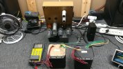
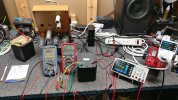
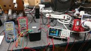
next chapter of "fun with higher than high voltage" begins. LCR meter on the ready plus variac.

heathkit w5m - 7.jpg
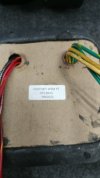
txf-tan future designation

heathkit w5m - 8.jpg
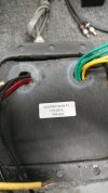
txf-blk future designation
 
heathkit w5m - 9.jpg
after documenting LCR results its time for some voltage testing

heathkit w5m - 10.jpg
starting at 100v mains and then increasing in 5v steps up to 130v mains. also documenting txf idle wattage unloaded.

in the view above some data syntax can be constructed prior to notes photos:
@100v 5.61w = 814v (ht 2nd) & 5.56v (6.3v heater) & 4.53v (5v rectifier heater)

spoiler alert, at 130v mains the 6.3v heaters are receiving 7.2v which seems problematic or reduced lifespan territory. perhaps adding a 0.22r 10w into the heater circuit, assuming 2.7a (each 6L6 at 1a, each 12au7 at 0.35a) at 115v mains.
 
Is the rebuilt transformer beefed up at all? The original was somewhat marginal and prone to failure, which I'm assuming is why you have a rebuilt one.
 
there was something mentioned about a common failure point, secondary center tap or something about a center tap in general but not much else in details especially overall history (previous owner hours used/abused). current owner had them up an running after purchase 10 or 20 years ago to verify they worked. then went into storage for future repair/update/rebuild or something, essentially waiting for the common re-cap stage in vintage audio lifetime.
 
the rebuilt mains txf will have a healthier lifespan once i balance out the bias/load vs custom b+ circuit design. thermal stress will be greatly reduced, not that i am into such things nor have a thermal camera on the bench at all times... that would be weird.

finding w-5m's with borked mains txf and healthy out-txf might be the winning combo. since the mains will need to be replaced, have the core removed but not rebuilt/rewound. instead use a 120/240 step up, commonly available under 100usd. yam under glass tube preamp project enjoying a 25va right now. add v-doubler circuit and spices to taste then let simmer for 20 minutes until side-b of favorite album, or something.


plus two or three pcb mount (if possible) 6.3v txf with center tap vs pseudo center which is also a possibility. one will feed 12au7 front end and the second will do outputs. for the perfectionist the potential third could be wired to the oddball triode section that has around 80-100v cathode offset instead of over-offsetting everything under 20v cathode.
 
going further down the r&d rabbit hole, could also use smps modules for independent and possibly fully isolated heaters (each triode, each output). in which case may as well do an smps or chopper circuit (buck regulator) to replace the mains txf completely. would need to do a diy custom module that could have variable vdc output (350v-550v) and variable current limiter (50ma-150ma) to dial-in the universal b+ module for either tube preamp or power amp turnkey designs. obviously easy smps safety can be achieved i.e. you aint blowing up this power supply (it wont let you). with the efficiency of GaN transistors things are looking good for thermal management.

hollowing out the original mains txf shell also creates a healthy sized heat sink surface although best not to drill holes or physically damage the shell, that would sabotage the visual vintage authenticity.
 
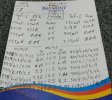
heathkit w5m - 11.jpg
numbers time. should be self explanatory although legibility could be better.

no dmm dcr for txf-tan yet, forgot to measure prior to the photo.

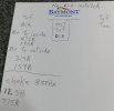
heathkit w5m - 12.jpg
"inside" refers to 6L6 closest to center of chassis, "outside" is the other socket. b+ center tap to anode/plate vs b+ to screen tap.

once again, txf-tan is on the to-do list for measuring.
 
voltage jumps: 974 to 512 and 980 to 510 should be obvious why. most dmm's cant measure past 1000v so used center tap ref instead.
 
to the center tap is useful for reading imbalance anyway.

if thats 6.65vac unloaded with 120 in, it will probably sit pretty close to 6.3 when normally loaded.
 
Back
Top Bottom