• The move to the new server is done. There are some software and database maintenance updates in process. This has us passing the hat around to help out. We appreciate any donations. Seriously, even a dollar helps. The payment page may be found here - https://www.audiokarma.org/support.html

Untapped Potential: Heath's W-5M

dcgillespie

Fisher SA-100 Clone
Subscriber
INTRODUCTION

Much has been written about these amplifiers ranging from their wonderful sound, to restoration needs, to their transformer failures. I’ve long been familiar with the W-5, with my first contact over 40 years ago when I was gifted one by a family member who built it in 1958. It included the larger Peerless 16458 output transformer, and after an initial checkup, still proved to run acceptably well at the time. Having only one however, it’s been in storage ever since. I always remembered it though as a piece where Heath really started stepping out on its own. A few years ago, I then acquired a second one from AKer Audiodon (RIP) that also employs the larger output transformer, creating a matched pair. It too has good transformers, and both are in decent physical condition, but certain aspects of the design have always left me lukewarm about these amplifiers, so it sat too.

The W-5 was released to great fanfare in 1955, being on exhibit at the Heath booth at the IRE Convention of that year, complete with its (unknown) designer in attendance. It’s design topology follows the classic W series designs that preceded it, but also continued with some uniquely Heath developed features that had previously been tested on some of their earlier amplifiers. This included the “Tweeter Saver” feature (output Zobel network) that started with the W-3AM, and an input impedance isolation network (starting with the W-4 series) — both being measures taken to keep their later Williamson offerings stable, versus the notable instability of their prior amplifiers. To this, Heath then put a real polish on the W-5. A new output transformer was developed for the W-5 (Peerless 16309, later upgraded to the larger 16458 transformer in 1957), and this time the transformer included convenient leads for each output tap, eliminating the terminal re-strapping required to change the output impedance in previous models with Peerless units. The chassis was refined with their new gold and black look, that for the first time also included a top cover, and even (long overdue) chassis ventilation holes. The output stage had additional stopper resistors added to accommodate the upgrade to premium KT66 output tubes, a new and simpler method was devised to balance them, and the front end was now populated with miniature tubes sporting tube covers. In the audio circuits, coupling capacitor values were altered again and other component values adjusted, while in the power supply, the rectifier tube was upgraded to a higher voltage 5R4GY type, and series connected filter capacitors now appeared in the first three filter sections. B+ voltages were elevated, power output increased, and for the first time, a very detailed presentation was made of the amplifier’s complete performance, covering no less than 7 pages in the Assembly Manual. For Heathkit then, the W-5 was their tour de force designed to draw a line in the sand regarding the company’s standing in the high fidelity industry. So, polished this amplifier was. Exact production numbers aren’t known, but judging by the number of examples generally available, it was certainly another Heath success story.

Recently however, I became interested in how Peerless transformers might have improved over time throughout their role in the Williamson story, since it was one of their transformers that was specified for use in Sarser and Sprinkle’s “Musician’s Amplifier”, which originally introduced the Williamson amplifier to this country. That amplifier solidified the fabled Peerless S-265Q output transformer as the gold standard for true Williamson amplifiers — an off the shelf production piece available in 1949 that is still revered even today. Since Heath was largely following S&S’s work with the Williamson, they also commissioned Peerless to produce the output transformers for their original WA-1, W-2M, and now W-5M amplifiers.

The period from 1949 to1957 however (when the 16458 was introduced) represented a time of great change and development in the design and production of output transformers. To see how that period might have brought improvements to the Peerless line then, it occurred to me that with my W-2 amplifiers I had already evaluated and modified earlier:

http://audiokarma.org/forums/index.php?threads/regilding-the-gilded-lily-heaths-w-2m.767851/

and the W-5 amplifiers I had in storage, I already had a 1952 benchmark and a 1957 bookend to look at, needing only a real S-265Q to complete the pair of bookends for the period, and an original W-5 16309 transformer to fill in the gap. Enter AKer Zackthedog, who not only had a spare authentic Peerless S-265Q, but also a Heyboer copy of that transformer, and an original 16309 as well that he kindly lent me for my investigation. It didn’t appear that any measured performance evaluation had previously been published on the W-5 (amateur or professional), so I finally had the motivation needed to get my W-5s out of storage and make them operational. As with the W-2s, their stock performance could then be fully analyzed and evaluated, along with that of the transformers Zack provided, to see if any real performance improvement had been achieved. Any opportunities for improving the amplifier itself could also be observed and potential solutions developed along the way.

As it turns out, the investigation showed that there were some surprising aspects of this amplifier’s design — hidden within it — that centers specifically around the Peerless transformers it uses. They were surprising enough to suggest that the W-5 — while no doubt a good amplifier as originally offered — has the potential to be much better.

As with my previous work on Heath’s W-2, W-3 series, and W-4AM amplifiers, this article is hardly meant to be critical of Heath’s efforts with the W-5 for the sake of being critical. 1955 was in the thick of some pretty heady times in the world of high fidelity design, with history showing even some of the best manufacturers of that day struggling mightily to maintain the best from their designs amid all the changes and new standards being established. This, in conjunction with the importance of marketing their product’s features for maximum appeal to the audio enthusiast of that day, made for some pretty intense needle threading to turn an audio buck. Therefore, there is little to be gained by arm chair quarterbacking today, the design decisions Heath made so long ago, since all the influencing factors have all but evaporated now. Those factors however have left opportunities today that the benefit of nearly 70 years of hindsight and modern approaches can provide better answers for, which can significantly improve the W-5 — both audibly and measurably.

The opportunities presented are divided into two basic groups: The first group is aimed at basic dependability issues only, and can be performed with minimal changes to the original design. The second group promotes maximum dependability, and is for those wanting to achieve maximum performance from the amplifier.
 
Register to hide this ad
OPPORTUNITIES

The design of the W-5 includes two auxiliary AC outlets, one of which is non-fused and always on when the amplifier is plugged into AC power, and the other being protected by the amplifier’s 3A fuse with its power controlled by terminals 6&7 of the Preamplifier Power socket. These terminals are either shorted together by a jumper for stand alone operation, or shorted together by the AC power switch of any external preamplifier connected to the socket to control AC power to the amplifier. For maximum protection however, the amplifier fuse should protect the amplifier only, and not any other connected devices. Therefore, modern operation of the W-5 amplifier dictates that at least the controlled auxiliary AC socket either not be used, disabled, or connected as a second unprotected/unswitched outlet, and that the fuse size is changed to no more than a 2A rating. A 1.5A slo-blo fuse has also been shown to give good service as well. These fuse sizes will then provide greatly improved protection for the amplifier from any significant operating fault, while also being able to handle the full continuous maximum power output of the amplifier. This change should be made before proceeding to any other modification.


DEPENDABILITY ISSUES

Voltage Surge:

The W-5 as designed operates with a B+ level of about 490 vdc at the OPT CT when operating from a 115-116 volt AC line, which is the design center AC line voltage the amplifier’s power transformer is designed to operate from. This B+ level is about 40 volts higher than that used in previous W series amplifiers, requiring Heath to employ a new higher voltage power transformer. As a result, they also changed from the 5V4 rectifier tube they had been using, to a 5R4GY type to provide a greater Peak Reverse Voltage safety factor. But the 5R4 is a quick heating type that also produces a greater voltage drop across it when loaded, so the combination of higher transformer voltage, higher tube voltage drop, and near instant heating means that before the audio tubes warm up, the turn on voltage surge now produced is quite high — some 600 volts or more, and lasts for nearly 15 seconds (based on using genuine KT66 output tubes) before the audio tubes start to conduct.

Heath accounted for the high surge factor by using series connected caps for the first three filter sections, producing a working voltage of 900 vdc for the first two sections, and 700 vdc for the third. This was necessary because there is very little resistance between these capacitor sections and the rectifier tube — 160Ω within the choke between the first two sections and a 100Ω resistor between the second two sections. With such little resistance, any current drawn by these caps would be very high if they were subjected to a significant over-voltage condition, and cause them to fail quickly. To prevent any damage to these caps then, their effective working voltage was increased to a value greater than the surge by using lower voltage caps connected in series for each section.

While this arrangement worked well for the first three cap sections, the three cap sections down stream from those aren’t so lucky. They are only rated for 450 vdc, while the dropping resistors serving them receives the full 600 volt surge voltage at turn on. Since the tubes these caps serve aren’t drawing any current during the initial surge period, that only leaves the leakage current drawn by the caps during this time to reduce the voltage presented to them. The dropping resistors are large enough in value to prevent any catastrophic damage to the caps, but small enough that the caps are still subjected to an excessive over voltage condition at turn on: these caps can see as much as 550 volts impressed across their 450 volt rating during the surge period before the audio tubes start to draw the voltage down.

Finally, the specifications indicate that the amplifier can operate from an AC line voltage of as much as 125 vac. Operation from this line voltage elevates the surge voltage even higher, and is the reason that the first two filter sections are rated at 900 volts. It is also the reason that the dropping resistors supplying the downstream caps are all specified as 2 watt devices, where 1 watt devices would normally suffice. The current flowing through them in this scenario elevates their dissipation level to the point that they need to be up-rated to 2W devices if a long service life is to be expected. Of course, this is still very hard on the downstream caps over time, and forms the basis for all the recommendations to upgrade these caps accordingly to improve the amplifier’s dependability.


Positive Heater Bias:

For stand alone operation, Heath instructs that the green/yellow CT lead of the power transformer heater winding be grounded in the amplifier. But this leaves a 100 volt (or more) potential across the heater and cathode elements in the phase inverter tube, which is not only the maximum H/K voltage limit for the tube, but also invites noise which can be generated by way of leakage between these elements. By providing an appropriate bias voltage for the heater circuit, it pulls the H/K voltage differential back from the limit that the tubes were designed to withstand, and also ensures the lowest possible noise from the amplifier. Even with positive heater bias however, the input 12AU7 tube should always be chosen for lowest noise operation. If the amplifier is used to power an external preamplifier, any connection from the heater circuit to ground must be eliminated in that unit when positive heater bias is added to the amplifier. Otherwise, the bias voltage will be shorted to ground.


Phase Inverter Grid Voltage

During the surge period, the grid of the phase inverter tube is subjected to over 500 vdc until both the AF Amplifier and Phase Inverter sections of the input tube warm up to produce normal operating voltages. This is not only a greater potential than the tube is designed to handle, but as the phase inverter section is first starting to conduct current, it effectively turns its grid into a second plate, causing it to conduct current which it was never designed to do.

Turn-Off Pulse

Most classic examples of cathode biased Williamson amplifiers using a tapped screen or genuine UL Class AB1 output stage will deliver a notable pulse (thump) to the speaker at turnoff. This is usually due to the inclusion of an output stage cathode bypass cap — necessary for a Class AB output stage to achieve best performance and lowest overall distortion. Its presence creates an additional LF pole (not present in the original Williamson design) that interacts with the existing poles and NFB loop to create the pulse produced at turn off. The original design of the W-5 produces such a pulse, which over time is very hard on the output tubes and output transformer as well.
 
Simple Solutions:

Many have written about dealing with the turn on voltage surge, invariably centering on increasing the working voltage of the electrolytic caps discussed. That is certainly a very workable solution for those caps, but usually prevents use of the FP type can cap originally used for those components, and doesn’t address all the surge related issues. An alternate approach eliminating all of these concerns is presented here:


Eliminating The Surge:

Replace the 5R4 rectifier tube with type 5AR4/GZ34.

2. Replace the 100Ω 7W power supply resistor with a 2.7K 2 watt metal film resistor.

3. Replace the 330Ω 7W output stage cathode bias resistor with a 360Ω 10W resistor.

4. Ensure that the two output stage cathode bypass caps are rated for greater than 50 vdc.

These modifications will allow the B+ to ramp up smoothly to the new operating voltage (about 525 vdc) after the audio tubes have warmed up, with virtually no overshoot. The new resistor values will maintain the original operating voltages for the small signal stages, and the proper quiescent current (bias) for the output stage.


Adding Heater Bias:

Remove the 100K 1W resistor connected across capacitor H at the triangle terminal. Replace it with a network consisting of a 68K 1W resistor, 33K 0.5 watt resistor, and .047 uF 400 volt capacitor. Connect one end of the 68K 1W resistor to the triangle terminal of capacitor H (S), and the other end to unused pin #1 of V5 (NS). Connect one end of the 33K resistor and .047 uF cap to pin #1 of V5 as well (NS). Connect the other end of these two components to the ground tab of capacitor H where the 100K resistor was originally connected to (S). Connect the Green/Yellow power transformer lead to pin 1 of V5 (S).

This network will raise the the heater circuit by about 80 vdc above ground. While this is not greater than the voltage appearing at the inverter tube’s cathode (which would be ideal), it is still appropriate enough to protect the heater/cathode insulation in the Phase Inverter section of V1, while minimizing noise in both sections of this tube, without exceeding the H/K ratings for any of the audio tubes in the amplifier.


Eliminating The Turn-Off Pulse

Use a small amount of adhesive to mount a small 120 vac coil DPDT “cube” relay with 10A contacts to the underside of the amplifier near where the power cord enters the chassis. The coil is connected directly across the AC power applied to the primary leads of the power transformer, with one set of NO contacts connected in series with the red output transformer lead connected to the power supply. Connect a .1 uF 1000 volt capacitor across the contacts used to prevent arcing and any small transient noise when the amplifier is shut down.


Dependability Recap

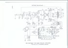
These modifications will prevent the otherwise high turn on voltage surge from being applied to the amplifier’s down stream electrolytic capacitors and phase inverter grid/cathode elements, reduce the excessive heater/cathode voltage in the phase inverter tube during normal operation, and eliminate the output tube turnoff pulse at shut down. Along with ensuring that the amplifier operates from the proper AC line voltage, this will ensure maximum life from these components and lowest noise operation, with minimal deviation from the original design. Due to the higher overall B+ now present, the amplifier will develop slightly greater power output as well. A schematic showing these modifications is shown at the end of this section.

However, there are also significant performance improvement opportunities available which will also enhance dependability even further when implemented. For those interested in making those modifications, do not perform the simple solutions presented here, as the issues they address will be covered again, but in a different manner within the more comprehensive discussion in the next section.

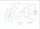
W-5 Simple Solutions.jpg
 
Last edited:
2. PERFORMANCE ISSUES

Lots of articles have appeared in print magazines over the years on how to improve the Williamson amplifier — either in its original form, or when upgraded with tapped screen/UL operation. Some have been marginally helpful, and some appear to be little more than self serving fluff pieces, but most fail to achieve the maximum performance for which the amplifier is capable. There are some improvements that can be applied to all versions of the Williamson in wholesale fashion, but to achieve the best performance, improvements must be developed on a case by case basis. And so it is with the W-5 as well, where the efforts of this project have attempted to achieve its best performance, and explain its many hidden mysteries in the process.


Output Stage

After restoration, both W-5 amplifiers of this project could easily meet or exceed all of the important performance specifications published for it. For this work, the following data was collected with the amplifiers operating from 115 vac to establish a base line to work from. The data presented is typical over numerous measurements of both amplifiers, with the differences between them being statistically insignificant:

@20 Hz = 22.56 watts RMS maximum power output at 2.5% THD.
@25 Hz = 23.77 watts RMS maximum power output at 0.55% THD.
@1 kHz = 25.00 watts RMS maximum power output at 0.32% THD.
@20 KHZ = 21.39 watts RMS maximum power output at 2.6% THD.

IM Distortion: 1.9% @ 25 watts, measured at 60Hz and 6 kHz mixed 4:1.

Frequency Response: +/- 0 db to 100 kHz.

Load Stability: Max capacitance loaded = .082uF. Unloaded = .015 uF.

Transient Response: Rapid settling under pulsed conditions loaded, notably slower unloaded.

Internal Output Impedance = 1.11Ω

Sensitivity: 2.25 vac for 25 watts.

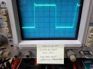
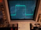
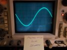
10 kHz Square Wave:

SAM_3745.jpeg

The only specification that I could not come close to reproducing is Heath’s claim of a Damping Factor of 40. With such a high figure for a mid 1950’s amplifier, it was surely generated by the old method of dividing amplifier internal impedance into the impedance of the tap it was measured at. Therefore, a damping factor of 40 implies an internal impedance of 0.4Ω at the 16Ω tap. This is a very low internal output impedance for any conventional vacuum tube amplifier — even lower than the figure quoted by S&S for their Musician’s Amplifier (0.5Ω) that employs a triode output stage and 20 db of NFB — versus the W-5 that uses a tapped screen output stage and only 18.1 db of NFB (both acting to raise internal output impedance over the original S&S offering). So it would seem that by either of these differences, the figure that Heath quoted for the W-5’s damping factor would be optimistic to say the least. Both amplifiers here returned an internal output impedance of 1.11Ω at the 16 Ω terminals when configured as the published design, indicating a more accurate (and realistic) damping factor of 14.4 when determined by the old method. A more true and honest damping factor of 1.44 results when a 16Ω speaker’s typical voice coil resistance (~10Ω) is added into the equation. But because this resistance varies with different speakers, the use of a Damping Factor specification has all but been eliminated today in favor of simply stating internal output impedance. Either way however, Heath was well off the mark on this one, while the remainder of the published specifications were ably met.
 
Last edited:
The 16309 Transformer

The same tests were then run again on one amplifier using the smaller 16309 transformer to determine what differences (if any) might exist between it, and its bigger 16458 brother — if only to gain some understanding as to why the transformers were changed out in the first place.

Much has been speculated as to why the change occurred, usually centering on some aspect of the 16309’s durability. If durability was an issue, the speculation offered invariably misplaces where the real blame is deserved. Since there were no other changes made to the amplifier's design when the transformer change was made, it also spawned the usual which transformer sounds better debates, and discussion as to whether the 16309’s reported inclusion of a small number of nickel laminations in the center of its lam stack provides any audible advantages or not. To provide some factual context, tests were conducted to help determine the real performance differences that exist between these two transformers. Those tests revealed:

1. Besides its smaller physical size, the 16309 transformer has a measured reflected primary impedance of 8600Ω from the full 16Ω secondary winding (open secondary test method, which is used through out this work), which is about 500Ω lower than that produced by the 16458 transformer. Also, both primary and secondary windings in 16309 display at least 40% greater DCR than the windings in the 16458 — a sure sign of the smaller gauge wire used in the 16309’s construction. All other features of 16309 transformer are identical to that of the 16458.

2. There are also high level dynamic differences between the 16309 and 16458 transformers as well. The biggest difference is the fact that the larger 16458 transformer can handle more LF power output without waveform distortion than the 16309 can, as would be expected. Therefore it produces slightly more power output in the lowest register, but only by a couple of watts.

The 16309 transformer appears to be an 20 watt transformer (only slightly larger than a Dynaco Z565), that can pass a visually undistorted 20 Hz waveform at 20.25 watts, before immediately saturating beyond that power level. The 16458 is a 25 watt transformer that can pass 28 watts before saturating under the same conditions.

In stock form, the amplifier can produce a maximum of 22.56 watts at 20 Hz with the 16458 transformer, providing about a 20% power reserve in the transformer before it saturates. In this scenario, the amplifier is running out of power before running out of transformer. Under the same conditions, the 16309 transformer produces a maximum of 20.25 watts at 20 Hz, indicating that the amplifier is capable of overdriving the 16309 transformer by about 10% or 2.3 watts at this frequency. In this scenario, the amplifier is running out of transformer before running out of power, but this difference would hardly be audible with normal use.

So was the transformer change a performance upgrade, or done to improve durability? The amplifier can just overdrive the 16309 transformer beyond its maximum power capability at 20 Hz, so the use of this transformer would hardly be considered an engineering faux pas. In fact, many amplifiers claiming high fidelity status were designed with far less transformer capability at 20 Hz, running out of transformer well before the amplifier’s full power is reached at that frequency. So if application wasn’t the issue, was the 16309’s apparent failure rate caused by a design deficiency within it then? That seems highly unlikely given the manufacturing and engineering quality that Peerless represents.

Whether Heath knew it or not, any early demise of a 16309 transformer can invariably be attributed directly to the design of the W-5 itself. As previously mentioned, a large pulse is produced every time the amplifier is turned off, generated by the various time constants of all the LF poles collapsing at different rates. The pulse signal is amplified by tubes that are still hot, and sent back through the NFB loop, which now makes matters exponentially worse: Because of the time issues involved at subsonic frequencies (delay), the NFB signal actually ends up becoming a positive feedback signal, so that the pulse is now greatly accentuated. In the W-5, it is made all the worse by the long R/C time constants Heath chose to use throughout the amplifier, and particularly into the output stage.

The large coupling capacitors there couple the high energy pulse into high current output tubes, and to a transformer that’s already pushed to its max at the low end of the normal audio band. This is particularly punishing to both the tubes and the transformer. With power no longer applied, the output tube heaters immediately start to cool off. Yet with sufficient reserve still available in the filter caps, the pulse created causes a very high (saturation level) peak current to flow in the output tubes that can then exceed the capability of the (now) reduced space charge remaining around the output tube cathodes — a charge that normally provides all the electrons needed for saturated current demands with fully powered heaters. This can then cause the pulse current to be partially drawn directly from the cathodes themselves, which is very damaging to them. Because only one (but always the same) output tube handles the pulse, this is also very often the reason that output tubes don’t wear out at the same rate in some designs.

The high current pulse also flows through the output transformer as well, immediately saturating it, which then potentially creates a high back EMF kick when the magnetic field produced collapses. This stresses the smaller wire used in the 16309’s primary winding, and its insulation with each occurrence. This pulse happens almost immediately, but every time after turn off, and over time, can take its toll on the transformer’s durability. Besides the turn off pulses, the amplifier’s design also allows any subsonic signals (rumble, tuning through FM carriers, etc.) and general power supply garbage to get through to the output stage as well, which only adds insult to injury.

The change to the larger transformer then was no doubt a durability move that ended up being a performance upgrade as a bonus. Whether Heath was aware of the underlying issues likely causing the problem is unknown. It seems unlikely though since it certainly would have been cheaper to address the real problem, rather than mask it with a larger transformer. Either way, its a pretty sure bet that any dependability issues with the 16309 transformer were never really due to its design or application at all, but the design of the W-5 itself. The larger 16458 transformer is simply beefier on the low end with beefier windings, and therefore better able to deal with the pulse conditions produced — so it has a better track record. But with proper attention to design, the 16309 transformer can no doubt be just as durable as its bigger brother, and actually improve the dependability of both transformers. To that point, the many extended full power tests at various frequencies throughout this project have not caused the 16309 transformer here to give even the slightest indication of putting up a white flag during such testing.

Closed loop frequency response, square wave display, and load stability are all virtually identical between the 16309 and 16458, but because of the 16309’s slightly reduced power handling capability, the distortion it produces is slightly greater at all frequencies as full power is approached. The increase is hardly anything that even critical listening could identify, but there none the less. The bottom line is that the 16309 is a very good transformer, which the 16458 slightly improve on by way of its greater power handling capability.

Finally, all the performance graphs presented in the two separate W-5 manuals (one for each transformer version) are absolutely identical, and are therefore obviously the result of the performance produced from the 16309 transformer. Those graphs do in fact align well with the results produced from tests when the 16309 transformer was installed.

With tests on the 16309 complete, the remainder of the work for this project was done with the larger 16458 transformer back in place, with this paper written and presented on that basis. Other than the performance differences noted above then, everything pertaining to the 16458 transformer going forward also applies to the 16309 transformer as well, unless otherwise noted.
 
Last edited:
Transformer Comparions

After initial tests were run on both of the W-5’s transformers, goals were then set to see if simple modifications could allow the W-5 to collectively produce: (1) an extended supersonic frequency response without peaking for a flat 20 Hz to 20 kHz frequency response and excellent 10 kHz square wave display, (2) a flat power response from 20 Hz to 20 kHz at 25 watts, (3) excellent low and high frequency transient stability, (4) good transient rise time, (5) absolute load stability, (6) identical performance at each output tap, and (7) while operating with enough NFB to limit distortion to less than 1% THD worst case within the audio range at no more than 1 db down from 25 watts (i.e., 20 watts).

That’s a pretty tall order, much of which is determined largely by the transformer itself. But amplifier design also plays a huge factor as well, so the challenge was on to see if any more performance was available through modification of the amplifier’s design.

With simple modifications to the W-2 amplifier, the Peerless 16277 transformer used in that amplifier has proven capable of taking a pretty darn good stab at achieving these goals based on a 20 watt power output rating. Excellent frequency and transient response, as well as square wave performance is achieved, although load stability — while certainly good — is not absolute. Max cap only loads are .05 uF on 16 and 8 Ohm configurations, and .15 uF on the 4Ω configuration. Power response is flat from 20 Hz through midband frequencies, but begins to fall starting at 6 kHz, being down nearly 1 db at 20 kHz. Distortion at 1 db below 20 watts is low, being well under 1% from 20 Hz, rising above that level only as 20 kHz is approached where distortion reaches 2%. Note that the 16277 transformer is a 25 watt transformer displaying a measured 9.2KΩ primary impedance to dual secondaries providing for 4, 8, and 16 Ohm configurations, with 50% taps on each of the two separate primary windings that are used to energize the screens as S&S did in the Gilded Lily with the S-265Q. Note also that the 50% taps provided with the S-265Q were never specifically designed from the outset as “screen taps”, since that mode of operation had not yet been introduced at the time that transformer was developed.

The S-265Q is a physically larger transformer rated at 40 watts, with a measured primary impedance of 10KΩ. Otherwise, it is identical in every respect to the features and construction of the 16277 transformer supplied with the W-2. When tested in the original W-2 setting (exactly duplicating the original Gilded Lily design), it’s performance was found (surprisingly) to be virtually identical to the performance produced by the 16277 transformer: The same frequency and transient response, square wave display, same overall distortion and load stability, and also the same power response as well, complete with the droop noted at 20 kHz. This is hardly an effort to put down the famous S-265Q but rather, to suggest just how good the 16277 transformer is that Heath provided in its place for the W-2. With such identical performance (at the power levels these amplifiers generate), the only real identifiable difference between the two transformers then is their size. As a result, in the W-2 setting, the 16277 comes off as a superb “mini-me” version of the Grand Poobah itself. It is safe to assume then that the 16277 is identical to the S-265Q in every way performance wise, except for physical size and power rating.

By comparison, the Acrosound TO-300 transformer in the W-3 series easily has a flat power response at 20 watts throughout the entire audio band and similar distortion performance to the S-265Q and 16277 transformers, but has varying frequency response, HF transient response, and load stability depending on which output tap is being used. The individual output impedance leads are convenient, but the inconsistent performance at each tap is notable, versus the very consistent performance from each output configuration of the Peerless transformers. The Acrosound transformer has two separate primary windings, a published primary impedance of 6600Ω, and dedicated UltraLinear screen taps located at 43% on each primary winding. Armed with all of this information then, it was on to the W-5s.

The 16458 transformer is the same physical size as the 16277 used in the W-2. It displays a very similar 9.1KΩ primary impedance, employs dual secondary windings, and has dedicated 50% screen taps as well. On the surface then, it would appear that the only significant difference between these two transformers is that the 16277 has its secondary windings each terminate with individual output terminals, whereas the 16458 uses a different approach that combines its two secondary windings internally, and then provides connections to those windings with conventional 4, 8, and 16 Ohm output leads. This change underscores a significant difference between these two transformers: With the 16277 transformer, the complete winding of both secondaries is used in the 4 and 16 Ohm configurations, and nearly 71% of each winding is equally used in the 8Ω configuration. In the 16458 transformer, both windings are also completely used for the 16Ω connection. But depending on how the secondaries are internally connected, it’s possible that only one secondary is used for the 4Ω tap, or some (possibly unequal) portion of both secondaries are used for the intermediate tap leads. Either way, it is simply not possible to create the secondary output configurations of the 16277 transformer when converting to individual leads for each output tap in the 16458 transformer. Also noteworthy is the fact that 16458 transformer has just one B+ lead for the complete primary winding, whereas the 16277 (and S-265Q) transformer has a separate B+ terminal for each of its two separate primary windings. Besides the winding configuration/connections, there could also be other differences between these two transformers. But based on these aspects alone, the 16458 transformer clearly has significant internal differences to accommodate the change from terminals to leads. Whatever the total differences are, collectively they produce significant performance differences as will be shown.

Of particular interest for this work then is the HF performance of the 16458 transformer. Both the S-265Q and 16277 transformers showed a rolloff in available power output at 20 kHz over that available at midband frequencies, but the Acro did not, nor do other highly regarded transformers in other designs. The quest was to find out why, but going against this was the fact that Heath had already admitted in the W-5 manual that the published power output capabilities for the amplifier at 15 watts or more at frequencies of 15 kHz or greater are not considered valid. This is dues to waveform distortion in that region that is sufficient enough to invalidate the readings taken with the peak responding RMS calibrated meters they used for testing. Such meters will quickly become inaccurate in the face of significant waveform distortion, so Heath’s statement would certainly make the FTC proud. Otherwise however, this up-front fact was an early indicator of the performance issues lurking in the W-5’s design.

Actually, it was really good on Heath, because before the W-5, Heath never specified power output with regards to frequency except in the W-4 series, where they stated that amplifier had a power output of 20 watts — but only at 1 kHz, with < 1% THD. The W-5 is rated as a 25 watt amplifier, but this power level is also only achieved at 1 kHz. In comparison however, the extensive graphs provided in the W-5’s manual show power output versus frequency over the full audio spectrum, and therefore start to air its dirty laundry: previous models with Peerless transformers also lack a flat HF power response as mentioned, but it was never disclosed because of the sparse specifications published for those units. Heath goes on at great length in the W-5 manual to indicate how important such information is, complete with what levels of distortion constitute High Fidelity performance, and even “extremely” High Fidelity performance. Likely, all of this was necessary to at least make sure it wouldn’t look like the new model was taking a step backwards in performance to previous models. No wonder it took seven pages to disclose it all!

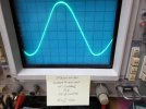
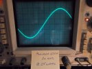
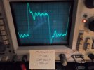
To get an idea of what Heath meant by their “invalid” power measurements, here is a pic produced by the stock design, relative to this discussion:

SAM_3768.jpeg


Relative to a pure 20 kHz sine wave, this waveform definitely takes on a somewhat contorted triangular look, putting a face on the waveform distortion that Heath mentions. It also gives credibility to their concern for using such a waveform as the basis for determining power output when a peak responding voltmeter calibrated for RMS indications is used. The voltmeter Heath used in determining the performance specifications for the W-5 was an HP 400-D, which represents this type of meter.

To eliminate Heath’s measurement issues, the power output measured for the base line information of the stock amplifier and indicated on the scope tag is based on using a wide band True RMS Voltmeter (HP3466A) with less than 1% indication error at 20 kHz. The THD measurement was made on a bench mule Heath IM-5258 THD meter.

Since the amplifier’s 20 kHz performance has a direct bearing on its ability to achieve the goals established, it was decided to investigate that issue first. And that’s where the real story of the W-5 begins………..
 
Last edited:
Initial Efforts

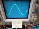
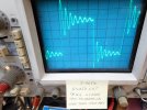
With a simple adjustment of the AF Amplifier stage step network and a few other changes, many of the stated goals could be achieved: (1) a flat frequency response to 20 kHz extending out to 70 kHz where it was 1 db down, (2) a flat top 10 kHz square wave with no ringing and good rise time — and for the first time, (3) absolute stability — and all using a simple single tap global NFB network, without the need for using the tweeter saver or input impedance isolation networks. And because supersonic response is identical at each output tap, a single tap network could be used from any tap desired with identical (excellent) results. This was all well received until a full power 20 kHz sine wave was then run up the flagpole, which yielded the following results at the on set of clipping:

SAM_3772.jpeg

The triangular waveform noted before is now more exaggerated, with the deformity beginning at right around 15 watts power output, just as Heath mentions in their manual. A quick recheck of modified W-2s showed no such peakiness of the waveform under the same conditions — just the slight roll off in power output at high frequencies, but never exceeding 1 db down from 20 watts even at 20 kHz.

So the concern Heath noted for frequencies and power levels above 15 kHz and 15 watts for the W-5 is real, making for two steps forward from the earlier transformers (convenient leads and absolute stability), but also a significant step backwards as well with the waveform deformity.

Tests were then made using different types of output tubes (KT77, EL34, KT88), fixed bias instead of cathode bias, increased quiescent current, and even a regulated power supply — but all turned in effectively the same results, with a triangular looking 20 kHz sine waveform starting at about 15 watts of power output. Converting to triode mode helped, but at a significant loss of power output of course.

The bottom line then is that with the original output stage, when using enough step network to produce excellent load stability, then high power HF waveform deformity is emphasized. And when the step network is reduced back to Heath’s values, then stability is reduced (although still workable), but high power HF waveform deformity is improved — although clearly not eliminated. So something is going on at high frequencies and high power levels in the output transformer, which is further affected by the HF contouring networks of the design. In view of all of this, it appears that Heath did a pretty good job of threading the needle, producing workable load stability with tolerable waveform deformation. But all of this just to get convenient leads for each output tap instead of re-strapping separate output terminals?

Acro surely had it’s supersonic frequency and transient response issues from its individual output taps, and now it appears that Peerless had its own (but different) issues when they converted to individual output taps as well. This will all be revisited in a bit, but for now, other notable design elements identified in the W-5 are presented.


Driver Stage

Another aspect of the W-5’s design that was curious was the use of a 2200Ω cathode resistor for the 12AU7 driver stage. This resistor is large enough (by about 4X the typical value used) so as to significantly over bias the stage (towards cooler operation) and limit its maximum low distortion output capability. The original Williamson concept has the driver stage being able to provide ample low distortion drive for the output stage and then some, whereas Heath went a different direction and intentionally limited the drive capability of this stage in the W-5.

In later kits, Heath also increased the value of the original 6800Ω B+ decoupling resistor for the driver stage to 15KΩ @ 2W as well. No specific reason was given for this change, but this would have the effect of further reducing drive capability of the stage even further, particularly if powering the matching Heath preamp. In that scenario, when power supply droop is also factored into the equation during heavy music passages, then driver stage capability becomes compromised enough so as to have literally zero reserve capability in driving the amplifier to full power output.

On the other hand, increasing the value of the decoupling resistor also has the effect of easing the stress on the decoupling cap it serves during the turn on surge period as well. Since the stress on this particular cap is very high with the original resistor value in place, this was the most likely reason for Heath’s change to the higher value. This reasoning would also be consistent with their inclusion of a Surgistor element in later kits to help address the surge as well.

One thing seems clear however and that is that the reduction in driver stage capability was apparently a coordinated effort to provide a measure of distortion cancellation with the output stage to lower overall distortion in the amplifier. The concept is certainly valid, but is usually rather tube dependent, requiring individual adjustment for the most effective results. Restoring more normal bias levels to improve the output capability of the stage did in fact increase IM distortion somewhat, so distortion cancellation does appear to be what Heath was trying to accomplish. That it was a design consideration at all however gives a clue as to just what Heath was dealing with in developing the W-5 amplifier.


Filtering For Small Signal Stages

In Sarser and Sprinkle’s original “Musician’s Amplifier” and “Gilded Lily” offerings, they used a 150Ω resistor to decouple power from the output stage B+ node to the driver and small signal stages, replacing the choke that Williamson originally used in that location (likely because he only used one choke ahead of the output stage). This resistance value was large enough to provide a reasonable level of decoupling for the driver stage, consistent with the least possible loss of B+ voltage, while also saving some weight and real estate on the amplifier chassis. Since S&S’s original power supply included two chokes on the power supply chassis, any actual filtering needs for the driver stage were likely of little concern at that point, so the arrangement worked well. In the W-1, W-2 and W3 series however, Heath dispensed with this resistor altogether, powering the driver stage directly from the output stage B+ supply. They also never used two chokes in the power supply as S&S originally did, but the configuration still produced a reasonably hum free amplifier. While S&S always retained the 150Ω dropping resistor for the driver stage, they too eliminated one of their power supply chokes as well for their Gilded Lily offering, stating that the amplifier was still completely hum free without it. Its elimination, and change to using a 5V4 rectifier tube (from originally a 5U4) completed the power supply changes they made for the Gilded Lily option.

By the time the W-4 series arrived, Heath was taking the idea of stability more seriously, and included a 1.5K dropping resistor (and filter cap section) between the output stage B+ node and the supply node for the driver (and earlier) stages — a value that provides real filtering benefits in that position.

With the W-5 however, Heath rather strangely added a small filter section after the power supply node supplying the output transformer B+, using a low value 100Ω 4W(!) resistor and series connected cap network after it to then provide power for the small signal stages and possible preamplifier it might power. With such a small dropping resistance in this filter section, it is providing little if any real filtering beyond that achieved by simply eliminating the resistor, and letting the capacitance of this filter section add to that appearing at the output transformer B+ node. It’s almost as if there was originally a small filter choke scheduled for that location, that was later scrapped for some reason, (cost, need, etc.), so a resistor of similar DC resistance was simply used in its place. But the insignificant filtering that approach provides along with the higher overall B+ voltage available in the W-5 means that a real opportunity was missed to add some worthwhile filtering benefits for the small signal stages.
 
Last edited:
B+ Distribution To The AF Amplifier/Phase Inverter Tube

In Dr. Williamson’s original design, the power supply nodes serving the input AF Amplifier stage and the phase inverter stage each have their own separate feed from the ~425 volt driver B+ source — a 33K resistor dropping the voltage for the AF Amplifier stage, and a 22K resistor dropping the voltage for the phase inverter stage. From information on his schematic, this provides separate but identical 320 volt sources for each stage to operate from. With direct coupling employed between these stages and an indicated plate voltage of 100 vdc for the AF Amplifier stage, it makes for workable operating conditions for the inverter stage, although not optimum for producing maximum peak-to-peak signal swing from each output. This is not a problem in the design however as only a few volts are required from each output to achieve maximum power output from the amplifier. However, the conditions also cause the H/K rating of the inverter section to be exceeded since the heater circuit is connected directly to ground.

In an ideal execution, it can be shown that a cathodyne inverter operates optimally when 1/2 of its B+ supply voltage is dropped across the tube. As this ideal condition becomes compromised, then one crest or the other of each output is compromised under conditions of maximum output from the stage. In Williamson’s case, with the stage operating from a 320 volt source, there should then be about 160 volts appearing across the tube, and 80 volts each across the plate and cathode resistors. Since Williamson indicates that the cathode terminal of the inverter in his design operates at 105 vdc, this punctuates the shift from optimum his operating conditions produce (only 34% of the supply voltage appearing across the tube), along with the excessive H/K voltage produced as well (max H/K rating = 100 vdc). In practice, it is always best to design for optimum conditions from the outset, which then provides for the greatest possible deviation from that condition by the usual variables of individual tube characteristics, component tolerance, and power supply sag with increasing power output, before performance becomes compromised.

Now when Sarser and Sprinkle adapted Williamson’s design for their Musician’s Amplifier, they altered the B+ distribution scheme for the AF amplifier stage so that the 33K resistor supplying the B+ node for that stage was no longer sourced from the driver B+, but from the phase inverter B+ node. This lowered the available B+ to both of these stages (typical AF Amplifier stage plate voltage now < 60 vdc), but also shifted the inverter to more optimum operating conditions (nearly 50% of the inverter’s supply voltage dropped across the tube), and resolved the excessive H/K condition as well, all with one simple change. The theoretical loss in the inverter’s undistorted peak output capability this change produced was more than made up for by the more optimum operating conditions it now enjoyed. Heath of course was largely playing follow the leader from S&S’s work, so the first four W series offerings all followed their B+ distribution scheme for the AF Amplifier stage lock, stock and barrel. But for the W-5M, Heath changed things rather significantly.

In this amplifier, Heath broke rank with S&S by no longer supplying the AF Amplifier stage dropping resistor from the inverter B+ node, now choosing to supply it and the inverter stage dropping resistor from a voltage source virtually equal to that supplied to the output stage. By topology, this is now similar to what Williamson originally did, but with two notable exceptions: (1) The voltage supply to these two resistors is now higher — about 50 volts higher than in Williamson’s original or Heath’s previous W offerings — and (2) The dropping resistance for the AF Amplifier stage is reduced from 33K to 15K. So the B+ supply for the AF Amplifier stage has been increased quite significantly by using a dropping resistor that is less than 1/2 its original value, no longer sourcing it from the inverter stage B+ node, and using the amplifier’s higher overall B+ voltage to source it from. Based on Heath’s indicated operating voltages, this move also provides nearly optimum operating conditions for the inverter, and increases the maximum output capability from both of these stages as well, although this was never an issue in previous designs to begin with.

The change is muddied however by the fact that the published operating voltages for these stages in the Heath W-5 manual are simply wrong. Operating from the correct AC line voltage, the AF Amplifier stage now actually operates from a supply source of 397 vdc (not 350 volts as published), with a plate voltage of 111 vdc (not 88 volts as published), while the inverter stage actually operates from a supply source of 370 vdc (close to the 380 volts published), producing an inverter cathode voltage of 118 vdc (versus 100 vdc published), and a plate voltage of 252 vdc (versus 280 vdc published). These changes may not seem that significant, but now move the inverter back towards Williamson’s original operating conditions (although at higher overall current levels) with the inverter tube now sinking only 36% of its supply voltage across it. The inverter’s excessive H/K voltage is now even more excessive as well.

It would appear then that Heath was playing with all of this for some reason, but failed to get their shoes and shoe laces all lined up properly when the final voltage table was published. The most logical reason is that the higher operating current of the input stage increased its static bias voltage, which then aided the problematic issues at high frequencies and high power output levels previously mentioned. Therefore, it likely produced some incremental decrease in the distortion of the overall design, although the effect on the input stage itself would be quite small.


Miscellaneous

Once again, Heath played with the time constants of the R/C coupling networks throughout the amplifier as previously mentioned. The approach produced a workable level of LF stability, but left the amplifier susceptible to damage over time. A better approach is available that can greatly improve LF stability, while also protecting the output tubes and transformer from damaging transients as well.


Performance Recap

Heath was clearly looking at anything and everything in developing the W-5 amplifier to achieved the specifications published for it. The extra effort all centers around the use of their latest Peerless output transformer, that for the first time provided individual output taps from a Peerless transformer in a Heath setting. Stability measures were increased, and new distortion reducing elements were introduced not seen in previous amplifiers. But for all of the hubbub, overall performance was not significantly improved from previous offerings, while new problems were actually introduced that were not present in previous models. Real performance improvement is possible however, which will be discussed in the next section.
 
Last edited:
A FRESH APPROACH FOR THE W-5M

Resolution of the dependability and smaller performance issues presented including: (1) the turn on voltage surge across the down stream electrolytic caps and inverter grid/cathode elements, (2) adding positive heater bias, (3) improving and simplifying small signal stage power supply distribution networks, (4) addressing the AF Amplifier stage B+ supply node (to promote proper inverter operating conditions), (5) optimizing coupling network time constants, and (6) optimizing driver stage bias — are all collectively rather straight forward in execution, requiring little discussion. The modifications presented for those areas will therefore be discussed in an overview of the complete modification coming up.

The big elephant in the middle of the room with the W-5 is its output transformer, which is where the high frequency/high power problem begins and ends in the design. The problem isn’t one of topology: a UL or tapped screen output stage can produce very high performance as various Acrosound and Dynaco amplifiers have shown. And the Peerless name represents quality without question. The problem is, this particular Peerless transformer and output stage don’t work very well together. They do well enough at low and midrange frequencies, and at high frequencies as well — as long as the power output requirement doesn’t exceed 15 watts. But that capability is hardly a definition of high fidelity performance.

The argument can be made that since little power is required in the upper audio register, there’s no need to go chasing after performance that’s already capable enough
as is — and that’s a perfectly good answer for some. But when better performance is readily available, it rings hollow if the best possible performance is desired.

The heart of the issue with the transformer is its screen grid taps. They’re placed at the same point on the primary winding as they are in the S-265Q and 16277 transformers, but something happened when the conversion was made to individual output leads in this transformer versus the output terminals for the individual secondaries of the earlier transformers. It would appear to be a leakage inductance or winding capacitance issue (or both) causing the dynamic signal appearing at the screen taps to effectively represent more than 50% of the plate signal, but only at high frequencies and high power output levels. This not only reduces the ability for the tubes to conduct current when it is most needed, but also causes them to be over biased during this time as well. The sides of HF sine waves then start to cave in and produce the more triangular looking waveform generated.

Further testing would be needed to prove this theory out, but some form of this is almost surely what’s happening: When using the taps, full power 20 kHz sine waves drag the power supply down only half as much as full power 1 kHz sine waves do, indicating that the tubes are simply not drawing nearly as much current at high frequencies as they do at lower ones. The same wave crest amplitude is produced at full power, but distortion now contains large amounts of odd harmonic distortion based on the waveform produced. Accordingly, reducing the cathode bias resistor acts to help restore waveform integrity somewhat, but then quiescent current goes off the chart once the signal is removed. Whatever the cause, it is an absolute fact that use of the taps to power the screen grids with either W-5 transformer absolutely degrades the high frequency high power performance of the amplifier.

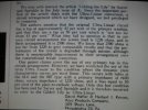
To this point then, it is interesting to note the response that Hafler and Keroes made regarding the S&S Gilded Lily effort in an open letter to Audio Engineering magazine shortly after the GL article appeared:

SAM_3731.jpeg

Based on test results then, it would appear that their comments ring true, and are not merely an effort to denounce S&S’s efforts as copycats in a competitive manner. In deed, the Acro TO-300 transformer does not display either the high frequency/high power distortion nor the high frequency power loss issues that the various Peerless transformers do, which suggests that the problem with the W-5 transformers then is not just one of transformer design, but of transformer specification as well — just as H&K state in their response.

Heath certainly knew about this issue from day one — hence the invalid power statement made in the original manual, that carries over into the 1958 manual provided with the 16458 kits as well — and for good reason: The tendency towards producing a triangular waveform at high frequencies and high power levels is even more pronounced with the larger transformer.

So the real question is: If Heath knew about the high frequency high power issue, why didn’t they take the opportunity to also address it with the introduction of the 16458 transformer? It would have been the perfect opportunity to solve two problems with one correction.

The likely answer may largely have been one of capability. By 1957 Hafler had developed his famous A-470 transformer for the ST-70 amplifier, which is the gold standard of transformer achievement regarding the goals set for this project. But that transformer is also a lower impedance device whereas the Peerless transformers in the W-5 are double the impedance of the A470 and more. That greatly complicates transformer design, so it may be that the engineering capability simply wasn’t there to have all the necessary design elements come together while also addressing the LF and HF issues identified. The most economical way forward then was likely to simply address the greater need (durability) by making a larger version of the original 16309 transformer. That resulted in the 16458 which resolved the transformer “durability” issue, but left the HF issue to be what it is, what it is, what it is.

Remember that by that time, Heath was married to the basic Gilded Lily transformer specifications (all but the W-3 used them), which originated from the original S-265Q transformer used in the Musician’s Amplifier. Therefore, they became an ongoing design standard even with the HF power droop it carried. Tapped screen or UL operation was the hot ticket of the day and Heath certainly still wanted to be a part of it since they helped to mainstream the concepts from the very beginning. But they also apparently did not want to go down the genuine UL path again either. For the W-5 then, they stuck with the S-265Q specifications, in spite of the new issues created when the winding configuration was changed to allow for individual output impedance leads.

It is also interesting to note that just a few years later then (1960), Heath purchased one of Acro’s Ultra Linear patents to put an end to the whole issue of what screen tap percent they could or could not use. This also allowed them the capability to freely market their amplifiers as Genuine UltraLinear designs when appropriate. Apparently by that time, it was more economical to simply purchase the patent rather than pay royalties to it……….

So the object of this particular exercise then boils down to determining how to make the best of the transformers offered with the W-5. Since Tapped Screen operation limits HF performance, and triode operation limits overall power, then the only other obvious choice left to consider is pentode operation. But it has its own concerns as well, which will be detailed a little later. However, there’s also another form of UL type operation available by way of employing a Partial Cathode Coupled output stage. What a huge game changer it is!

Such a notable design change is no doubt cause for great consternation among classic W-5/Williamson aficionados. But before writing this recommendation off as just another hack job on a classic vintage design, consider the tremendous success that ARC has had in using this concept in all of their vacuum tube amplifiers. Others have used it as well. Also, this recommendation is not based on some biased whim of subjective think, likes, or dislikes but instead, is based purely on gathered facts. The bottom line then is that the performance of the original amplifier is compromised by the issues presented, while the recommended modifications resolve those issues with very audible and measurable benefits.

The W-5 was a capable amplifier when produced back in its day — its published specifications certainly prove that. But there’s always that hazy relationship between measured performance and sonic performance, where sometimes they coincide well, and sometimes have no relationship at all. I give more thoughts on that in the Epilogue. With the W-5 however, and the demonstrable improvements that can be had when converting it to Partially Cathode Coupled operation, it makes the decision to modify the amplifier as presented basically a no brainer.
 
MODIFICATION OVERVIEW

With the issues of the stock amplifier all laid out, the modifications for resolve with improved performance can now be presented. Schematics and pics will be presented at the end of this work:

1. In the power supply, the stock rectifier tube is maintained, as the use of any other common type produces greater B+, which with the modifications presented then starts to produce a lop sided power response. B+ dropping resistance values are altered for more effective filtering, proper phase inverter stage operating conditions, and simplified B+ distribution. Zeners are installed to limit the turn-on voltage surge to the voltage rating of the down stream electrolytic caps they act to protect. When normal operating voltages are reached, the Zeners effectively disengage from the circuit. Once disengaged, they then provide a trickle current to produce a 90 volt heater bias, elevating the heater voltage above that now appearing at both the AF Amplifier and Phase Inverter stage cathode elements. Noise is minimized while the H/K potential of both sections is maintained within the max rating for the tube. Finally, a small diode is added across the grid/cathode elements of the inverter tube to limit the high potential between these elements during the warmup period. The diode disengages when normal operating voltages are established. With these modifications, it is now safe to continuously operate the amplifier with all audio tubes removed (just the rectifier in place), since the well over rated Zeners employed operate at only 38% of their rating when engaged under worse case conditions at turn on. The amplifier must operate from an AC voltage source of 115-116 vac to preserve the life of the power transformer and produce normal operating voltages.

2. A new negative bias supply must be installed, as the original cathode bias scheme is eliminated, and the output stage now operates with fixed bias. This supply must deliver an output of about -38 vdc. A small, lightly loaded low current 25.2 volt transformer delivers the needed voltage through a bridge rectifier.

3. An EFB™ Screen Grid Regulator is employed to supply the correct operating voltage for the screen grids (315 vdc) when operating as pentodes into the reflected load provided by the W-5 output transformers. The regulator properly maintains the voltage relative to any droop created in the B+ supply, or increasing current drawn by the screen grids with increasing power output.

4. The value of the coupling capacitors used into and out of the driver stage are swapped for more effective LF stability and output tube protection. When Heath intentionally over biased the driver stage (limiting its low distortion output capability), it meant that the coupling capacitors into the output stage needed to be increased significantly to prevent any further loss of LF drive across the R/C coupling networks into that stage. If significant, it would then increase distortion or prevent the amplifier from producing full power output at low frequencies. The capacitors were therefore increased in value to prevent that from happening. By returning proper bias levels to the driver stage (reducing the value of the cathode resistor appropriately), it makes for plenty of LF drive capability even across an output stage R/C network that now has 1/10th the time constant of the original network at this location. At the input to the driver stage, the opposite change occurs so that the time constant there is now 10X that of the original value at that location. Not only does this arrangement now provide good protection for the output tubes, but LF stability is also enhanced because the spread of the time constants into and out of the driver stage is now increased from a factor of about 2, to nearly 50. LF stability is enhanced even further due to the lack of any need for an output stage cathode bypass cap, completely eliminating one LF pole from the design. The distortion cancellation effect of the driver stage is eliminated of course, but is now no longer needed as well be shown.

5. Excellent HF transient and absolute load stability are achieved by using a “heavier” step network (lower resistance, higher capacitance) in the plate circuit of the AF Amplifier stage, retaining the 15K input grid resistor for that stage, and using a similar value phase advance cap in the NFB network. In this case, no series resistance is necessary in the step network, as the plate resistance of the tube itself suffices for that need. HF tailoring is also accomplished by retaining the larger than average g1 stopper resistors used in the output stage as well. No other HF shaping remedies are required, allowing the input impedance isolation network, and output transformer secondary Zobel network (Heath’s “Tweeter Saver”) to be eliminated from the design.

6. The output stage is configured to operate as a Partially Cathode Coupled design by grounding the 4Ω output tap, and returning the Com and 16Ω taps to the proper output tube cathode circuit. This prevents use of the amplifier with any grounded or interconnected Common speaker connections between stereo channels, but this is usually not a problem in practice. The output tube screen grids now operate at 315 vdc, so the required grid bias voltage is significantly reduced from 47 volts of cathode bias in the original design, to 29 volts negative grid bias in the modified design. This then achieves the proper (lower) quiescent cathode current of 43.6 mA per tube. The relaxed bias voltage eases the driver stage requirements as well, although that advantage is curtailed somewhat by the local NFB applied around the stage. Due to the biasing network used, the original design requires a 100+ volt peak-to-peak push-pull drive signal into the output stage to develop full power output, while the modified output stage requires just 86 volts peak-to-peak. This overall drive reduction further enhances the headroom created by the re-biased driver stage to ensure plenty of low distortion drive is available at 20 Hz for full power output.
 
MODIFICATION DESIGN CONSIDERATIONS


Output Stage Operation

In the original design, the KT66 output tubes idle at a plate current of 57.5 mA each producing a Pd of 24.15 watts. This is a true measured current draw, and not that derived from the Heath voltage chart which contains numerous errors. KT66 tubes are rated for a maximum of 30 watts Pd, so they operate at 80.5% of of their Pd rating in the amplifier.

In the modified design, the output tubes idle at a plate current of 41 mA each, producing a Pd of 20.7 watts, which is a significant drop from that of the original design. The recommended 7027A tubes are rated at 35 watts Pd, so they operate at just 59.2% of their Pd rating. Quality 6L6GC tubes have also been used with good success in the modified design as well, with those tubes operating at just 69.0% of their Pd rating. Excellent life expectancy can therefore be expected from either tube.

Ultimately, any of the 6L6 class tubes rated for 30 watts Pd or more will work very well in the modified amplifier, with all easily producing more than the rated 25 watts of power output. The original KT66 tube produces no more power in spite of it’s larger cathode surface, and also draws the most heater current (1.25A). Two of these tubes consume an extra 4.4 watts continuously from the power transformer’s heater winding over other 6L6 class tubes, making it the least efficient, but likely longest lasting tube in at least the original design. Finally, the KT66 also produces the greatest amount of distortion as well in both the original and modified amplifiers — achieving 0.1% THD in the modified amplifier at 1 kHz at 20 watts output. The 7027A achieves the lowest distortion at .056% THD under the same conditions.

This is hardly an effort to dump on the famous British valve, but merely provide some solid facts regarding its performance in place of the usual subjective fluff offered.
The original UL concept and S&S Gilded Lily effort were both developed using American 6L6 class tubes, so it follows then that they would produced the best overall performance in the original designs. For the modified amplifier, the 7027A tubes used requires rewiring of the output tube sockets, since the original build uses pins 1 and 6 on these sockets as tie points, where as the 7027/A tube uses these terminals for additional grid connections. Use output tubes that best suit your needs, but for best performance they should be well matched.


Power Supply

The modified amplifier draws a total of 114 mA from the B+ supply under quiescent conditions. The voltage indications from Heath’s table in the W-5 manual suggest that the original design draws 133 mA, but due to the inaccuracies of that table, actual measurement with multiple tube trials puts this more typically at 145 mA (and more with a preamplifier connected that draws its power from the amplifier) — both measurements being made when operating from a 115 vac line. With the power transformer’s HV winding rated for 140 mA total, and the amplifier alone drawing 3.1A of current from the heater winding, it can be seen that connecting the Heath WA-P2 preamp to the amplifier now stress the heater winding to the max, and the overloads the HV winding even further. The toll on power transformer life by the original design then is hardly to be unexpected. The reduction in B+ current draw of the modified amplifier causes the B+ level supplied to the output transformer to rise to 510 - 515 vdc. This coupled with the reduced heater power consumption produces notably cooler power transformer operation.


EFB™ Application

Some may notice that an EFB Control Grid Regulator is not used in this application. That’s because there is little benefit from its use in this case.

In Class AB applications, full EFB control offers the most performance improvement when small to medium power high transconductance tubes are employed to produce nearly the maximum power output for which they are capable, especially in stereo applications where a conventional power supply serves both channels. In such cases, output tube plate dissipation often runs near maximum tube ratings for a number of reasons, not the least of which is to help control distortion under high power conditions when power supply voltages have dropped. Uncoordinated changes in control and screen grid voltages can have a significant impact on the power and distortion produced under those conditions, allowing full EFB operation to be highly effective in those scenarios. The circuit continually maintains optimum operating conditions for the tubes under all power supply conditions, eliminating the otherwise high quiescent current levels originally required, and extending tube life in the process.

For the application presented here however, it is a mono unit employing output tubes with about half the transconductance of more modern types, operating into double their normal reflected load, idling at just 59% of their Pd rating, and producing about a third of their maximum power output capability. Such a scenario greatly reduces the need and impact that an EFB Control Grid Regulator will have, so only an EFB Screen Grid Regulator is employed to produce the correct operating potential for that grid.

Finally, some may question if EFB could have simply been applied to the W-5’s original output stage to improve its performance. It could have, but it would have been a pointless exercise. EFB can only account for changing DC operating conditions from the use of practical power supply designs — not for inherent issues with the AC voltage appearing at the W-5’s output transformer screen taps. That can only be addressed through the design of the output transformer itself.


DC Bias and Balance Adjustment

Because each half of the output transformer secondary is connected in series with the cathode circuit of an output tube, how the secondary is loaded can affect voltage measurements made at the cathode test points. To ensure proper accuracy then, the following precautions must be observed: (1) Make sure there is nothing connected to the 4 or 8 Ohm output taps when such measurements/adjustments are made. (2) The Com and 16Ω terminals should be shorted together, and the adjustments made in the usual way with no signal applied to the amplifier. Note that there are different voltage levels required at the output tube test points based on which output transformer is used. The difference is due to the difference in secondary DCR between the two transformers. Therefore, different optimum voltage levels are required to achieve the same quiescent current flow through the tubes regardless of which transformer is used.


Turn-Off Pulse

In the modified amplifier, there is no output stage bypass cap, so that LF pole has been eliminated from the design. The time constants of the coupling networks into and out of the driver stage have also been adjusted for maximum LF stability, and significant rejection of subsonic signals applied to the output stage as well. Therefore, no significant output pulse is produced when power is removed from the amplifier.
 
Feedback Level

Tests for feedback effectiveness were performed on both the original and modified amplifiers. All tests were conducted at a power output level of 20.0 watts at 1 kHz from the 16Ω tap, producing the following results:

For the stock W-5, the screen taps of either transformer provides 7.2 db of NFB based on gain reduction, producing a 2.23X reduction in distortion. The global feedback loop operates with 18.1 db of NFB, producing an additional 8X reduction as well. Combined, these two loops represent a total distortion reduction capability of 25.3 db for a 17.8X reduction. Based on a measured 4.0% THD before either of these loops are applied (which includes any distortion reduction produced by the driver stage), this suggests that the stock amplifier should produce 0.22% THD after the loops are closed. In fact, the results of this exercise agree very closely with the measured results produced by the stock design (0.21%), and the graphs provided in the W-5 manual as well.

In achieving this performance, the distortion contributed by the output stage is largely in keeping with published data. Operating as designed but with the global loop open, the amplifier produces 1.8% THD, which is close to the 1.6% figure that RCA published for similar operating conditions, but using genuine UltraLinear specifications (43% screen taps).

By comparison, the modified amplifier employs push-pull NFB in the cathode circuit of the output stage, which produces 4.2 db of gain reduction at the specified quiescent current level. Normally, this would only produce a distortion reduction of 1.62X, but because of the push-pull connection, the reduction factor is squared so that distortion is actually reduced by a factor of 8.40 db, or 2.63X. Using just this feedback alone, open loop distortion is reduced from 0.94% to 0.36% under the test conditions specified. The modified amplifier also employs a global loop that provides 17.3db of feedback, producing a 7.35X reduction as well. Combined, these two loops reduce distortion by a total of 25.7 db, or 19.3X.

When this total reduction capability is applied to the modified amplifier’s initial distortion of 0.94%, it indicates that the design should produce a distortion of .049% with all loops closed. In fact, the modified amplifier produces .056% THD which is about 14% greater than the analysis predicts.

This discrepancy is due to use of both balanced and unbalanced feedback systems being applied to the amplifier. Slight differences in distortion are produced in each half of the output transformer secondary under Class B conditions (<.04% difference) due to the balanced feedback system acting on each output tube individually during this time. Normally, this would easily be ironed out with the use of balanced global loops and cross coupled driver stages, which is the beautifully elegant arrangement that Bill Johnson of ARC fame applied to all of his tube amplifiers. But with the more economical approach used here, only one global loop is employed. As a result, it operates in a somewhat hamstrung fashion without its opposite mate in place to apply feedback from the other half of the secondary. Still, there is enough coupling within the output transformer that the one global loop employed is nearly 88% effective all by itself.

The modified amplifier then operates with nearly the same amount of total NFB (+0.4 db), but produces only a quarter of the distortion produced by the original design. That’s because the Partially Cathode Coupled output stage has basically 1/4 the open loop distortion to begin with. Also, even with the 4.2 db loss in gain that the push-pull feedback connection produces, the modified output stage still has 2.7 db more gain than the original output stage does. When this extra gain is combined with the 0.8 db reduction in global NFB from that of the stock design, it increases the input sensitivity of the modified amplifier by 3.5 db (1.5X), so that it now requires only 1.50 vac to produce 25.0 watts, versus the 2.25 vac that the original design required to produce the same power output level.


Partially Cathode Coupled Operation (Modified UL)

The use of this type feedback fundamentally changes the operating conditions of the output stage besides simply being a convenient method of injecting NFB signals into it. That’s because the NFB signal is now being applied to both the control and screen grid elements of the tubes. The connection also raises the impedance that the output transformer presents to the output tubes (to nearly 10KΩ) because the secondary winding has now effectively become part of the primary winding. Being a form of UL operation, Williamson facetiously dubbed this approach as producing a “Super UltraLinear” mode of operation, but it does in fact produce some very real and beneficial results.

Without the cathode feedback connection (i.e., conventional pentode operation), the modified amplifier can produce a very low open loop distortion of 0.47% at the lowest distortion operating point. Unfortunately, this also results in a quiescent plate current of 55 mA and plate dissipation of 26.1 watts per tube, which is on the high side for most 6L6 class tubes. With push-pull cathode feedback however, quiescent current is reduced because the overlap period where Class B operation commences is linearized in a way that global feedback simply cannot do. That’s because like UL, the connection effectively changes the characteristics of the tubes. As a result, the lowest distortion operating point now only produces a quiescent plate current of 41 mA, and a plate dissipation of just 20.7 watts per tube. This produces real savings in terms of tube life and power consumption, opens up the possibility of using a greater variety of tubes, and reduces overall operating temps as well. With all loops open, distortion starts from a higher level (double) with the lower current operating point (0.94%), but because of the exponential effectiveness of the push-pull feedback connection, the amplifier produces even lower distortion (0.36%) with just the push-pull feedback in place.

So the Partially Cathode Coupled output stage produces less distortion than conventional pentode operation, and 5X less distortion than the original tapped screen output stage produces. Besides all the other benefits noted, it also provides a significant distortion reduction advantage at the frequency extremes, where transformer losses start intruding on performance. The output stage so configured develops 9 watts of Class A power output before shifting to Class B operation.


Small Signal Tube Selection

For best performance, both sections of the driver tube should be well matched to each other. Matching of the two sections within the AF Amplifier/Phase Inverter tube has no significance in a Williamson design, but is worthwhile between stereo amplifiers.


End Of The Road

With that, presentation of the stock design issues, and explanation of the modifications for resolve and improved performance presented are complete. Pics and schematics are presented at the end of this work.
 
Last edited:
Final Performance Modified Design — 16458 Transformer

Power Output: 25 Watts RMS from 20 Hz to 20 kHz undistorted power response.

Distortion: < 1.0% THD from 25 Hz to 20 kHz at 25 watts. (< 0.1% at 1 kHz typical)
Note: Core saturation rises quickly below 22-23 Hz, producing ~2.3% THD at 20 Hz at 25 watts (~ 3X that produced at 25 Hz at this power level).

IM Distortion: 0.40% at 25 watts. Test signal = 60 Hz and 6 kHz mixed 4:1.

Frequency Response: +0.1/-0 db 20 Hz to 20 kHz. Down 1.0 db @ 70 kHz.

Sensitivity: 1.50 vac for 25 watts output.

Internal Output Impedance: 1.12Ω @ 16Ω output.

Stability: Absolute, with no amount of capacitance only loading causing sustained oscillation on any output tap.

Transient Response: Flat top 10 kHz square wave loaded with standard resistive load, or unloaded. Rapid settling when pulsed under any load condition.

10 kHz Square Wave:

SAM_3799.jpeg


Final Performance Modified Design — 16309 Transformer

With the following exceptions, all performance specifications for the modified amplifier with the 16309 transformer are the same as those with the 16458 transformer:

Power Output: 20 watts RMS from 20 Hz to 20 kHz undistorted power response.

Distortion: < 1% THD from 28 Hz to 20 kHz at 25 watts. (< 0.1% at 1 kHz typical)
Note: Core saturation rises quickly below 26 Hz, producing ~ 3.1 % THD at 20 Hz at 20 watts (~ 4X that produced at 28 Hz at a 25 watt level).

Internal Output Impedance: 1.16Ω at 16Ω output.

10 kHz Square Wave:

SAM_3812.jpeg


Schematic Details

Unless noted, all resistors are 0.25 watt 5% CF types. Higher wattage resistors are 2% MF. Output tube current sense resistors are 0.25 watt 1% MF. Output tube coupling caps are 630 volt mylars. Phase Inverter couplers are 400 volt mylars. Feedback and Step network caps are 5% 500 volt Micas, specified in mmF values. All mirror image (i.e. push-pull) components should be matched to within 1% if possible, and stereo units should have relative components matched to within 2%. All voltages +/- 10%. The recommended EFB Power Mosfet is a plastic device that can be mounted directly to the chassis with a small amount of silicone grease, using the screw securing the one terminal T-Strip under the choke.

.
Test Point Voltage

16458 Transformer = .061 vdc +/- 2%.
16309 transformer = .067 vdc. +/- 2%.
 
Last edited:
Epilogue

So much has been learned about the W-5 amplifier that was never anticipated at the outset. As a result, what was just going to be a quick testing exercise turned into a full blown project. At the very least, the W-5’s transformers have been shown to be capable of delivering some very fine and improved performance over previous Heathkit Peerless offerings — now achieving absolute stability without the need for any of the add-on gimmicks that Heath used and achieved far less stability with. While their ultimate performance capability is clearly improved, ironically it is the use of their own screen taps that produces the greatest hinderance to significantly better performance in that design. Looks like the advertising gurus won out over the engineers once again!

One other interesting difference was noted between the 16277 and W-5 transformers as well: distortion performance at the frequency extremes is reversed between these transformers. That is, based on a reference power level of power level of 20 watts, the modified W-2 amplifiers produce very low 20 Hz THD (0.55%) and rather typical 20 kHz THD (2.0%) — both at 1 db down from 20 watts. Both W-5 transformers however — at the same power level — produce greater 20 Hz distortion (basically double), but notably less 20 kHz distortion (< 1%) than the 16277 transformer does at these frequencies. Overall, these differences are minor enough in the bigger picture, and may even have been expected with the 16309 transformer. But the fact that they were also present the bigger 16458 transformer underscores the significance of the internal changes required between the earlier transformers, and those for the W-5 to accommodate the individual impedance leads.

It might be interesting to see how the S-265Q and 16277 transformers would perform in the modified W-5 amplifier, but such testing would be rather pointless since only a 16Ω output is possible when push-pull local NFB is employed with those transformers.

Finally, while it hasn’t been investigated, it is an almost certainty that the power drop off noted at 20 kHz with the S-265Q and 16277 transformers is not a transformer issue, but a result of using their 50% taps for powering the screen grids as well. They don’t display the high power high frequency issue that the W-5 transformers do when their taps are used, but do display a power loss at high frequencies none the less. It would seem then that the golden nugget of H&K’s response is quite apropos when they state (regarding use of the S-265Q): “We know that 2500 Ohms is too far off from 1220 to give comparable results (to that of UL-dg) and that the performance of the circuit is degraded through misuse, although there is measurable improvement in their arrangement over the conventional triode arrangement.” (emphasis mine) In other words, while use of the Peerless 50% taps for the Gilded Lily effort with either the S-265Q or 16277 transformers do in fact result in improved performance over the triode connection of the original design, they do not achieve the full benefits of genuine UltraLinear operation, which the taps attempt to emulate. Testing of Heath’s W-2 and W-3 series amplifiers has born this out, and has shown that the “degraded”performance primarily occurs at the high frequency end of the audio spectrum.

Ultimately then, all of the original goals established have been well met with the modified design except for distortion performance at 20Hz, where it is still over 1% at 20 watts at that frequency (1.4%). This is a product of transformer limitations for which little can be done within the scope of this project — but the goals are all met quite handily when 25 Hz is used as the lower limit for the distortion specification. Other benefits have been achieved as well, as documented throughout this text. The amplifier is more sensitive now — bringing it in line with many other vintage power amplifiers — and steady state power consumption has been reduced by over 17 watts (heater and B+ combined). Overall performance has been increased (original issues resolved) with more power, less distortion, and greater stability, with no downside issues created in the process — the very definition of a win-win outcome.

It’s always hard if not suspect to subjectively rate the outcome of one’s own work, so I’ll stay away from the usual superlatives used to describe the modified amplifier’s performance in the listening room. The stock W-5 certainly sounds good on my 101 db efficient Cornwalls, and does everything it is supposed to well enough. And while it does all of that, it doesn’t sound particularly special (to me) either — special being that quality that goes beyond the usual sonic measures observed to one that you instantly recognize when you hear it, but can’t put your finger on to define. Over the years, I’ve attempted to define that quality in an amplifier as one that is full, dynamic and balanced sounding, with an unmistakeable sense of ease and effortlessness in its presentation throughout the audible register. This kind of sound doesn’t come from simply having 100X the power you could ever need, but one produced by an amplifier where every aspect of its design works in perfect harmony with every other aspect of the design, with a shoes and shoe laces type fit. The modified amplifier does exactly that now: The improved measured results are not achieved by the usual quick-fix remedies of cranking up the quiescent current of the output tubes, adding gobs of extra feedback, or supplementing the power supply with mega-joules of extra caps mounted all over the chassis. The original design was simply evaluated stage by stage to determine the individual contribution of each stage to the end result. Modifications were then developed as necessary to ensure that all stages would ultimately work to their best capability and together as a team in producing a new and better result. By comparison, the original design — unlike its predecessors — is more of a square peg into a round hole effort that forces a performance outcome from circuit elements that don’t fully support each other in producing that outcome. In my humble opinion, results from that kind of design approach are invariably audible — even if not definable — and not in a good way, removing elements of realism and presence from the sound. For me, the modified amplifier now displays the wonderful kind of sound described in spades, making for a new W-5 amplifier — one with an improved sonic experience and more engaging sound in the listening room, and one that can back that up with significant measurable improvement in the lab as well. The fact that it also is no longer prone towards self inflicted damage and destruction? Priceless!

Happy listening!

Dave
 
Last edited:
W-5 Modified Design.jpg
W-5 Modified Power Supply.jpg

Below: Original Design:
W-5 Original Design.jpg

Below: 25 watt 20 kHz sine wave -- no comparison to that produced by the original design. Less than 1% THD here:
SAM_3801.jpeg

Below: Even 20 Hz at 25 watts isn't too shabby -- about 2% THD here:
SAM_3804.jpeg

Below: Absolute stability is now achieved. Worst case cap only load shown:
SAM_3800.jpeg

Below: Here's one I've always wondered about for longer than I can remember. No disrespect meant, but S&S never provided a pic of a 10 kHz square wave through their Gilded Lily effort, and here's likely why! This is an exact copy of the GL design with the S-265Q installed -- and loaded!
SAM_3756.jpeg

Below: Sorry about the fuzzy pic, but unloaded (shown), the GL can only handle a maximum of .0022 uf, and it's already clearly distressed as is:
SAM_3752.jpeg

Below: By comparison, here's the modified W-5 unloaded:
SAM_3798.jpeg

Below: The underside of one of the modified amps. A few components were tweaked after this pic was taken, but for all intents and purposes, this is it:
SAM_3794.jpeg
 
Last edited:
Back
Top Bottom