• The move to the new server is done. There are some software and database maintenance updates in process. This has us passing the hat around to help out. We appreciate any donations. Seriously, even a dollar helps. The payment page may be found here - https://www.audiokarma.org/support.html

Untapped Potential: Heath's W-5M

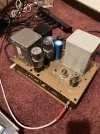
I have finally finished the two I've been working on for a few months. Both passed the dim bulb test with no tubes, and then with the rectifier. Voltages with the rectifier in place all looked good, so apparently no major wiring issues. I've put a full complement of tubes in one, and tried to set the bias. Like others have discussed in this thread, I had to tweak the resistors in the bias circuit to get enough negative bias voltage. That done, I hooked up a speaker and a WA-P2 preamp (after bypassing the heater balance circuitry, and I'm using my phone through a USB dongle for a source. (I'm doing all this work where I'm living away from home on weekdays due to taking a job too far for a daily commute.) I have a couple of problems and questions....
1. When I turn the preamp volume up past a fairly low volume, the amp starts motor boating. Sometimes it stops if I turn down the volume, other times I have to disconnect the preamp. Although the preamp is totally unrestored, I suspect the problem is in the amp. I was able to get the amp to begin motor boating by wiggling one of the 12AU7s to generate dirty socket static. Once that started I had to turn off the amp. Any thoughts where I should start looking?
2. The bias transformer I used has a center tap on the secondary. It is not wired to anything. Should it be?
3. The 3k ohm/2W resistors have gotten very hot and are already discolored after less than an hour of run time. I measured the voltage across them, about 55V, which calculates out to about 1W. Any issue here?
4. I am also using the Sheldon Stokes board, modified with the help of Nerdorama. Some of the caps on the board get a little warm. Not hot, but warm. Issue?

I'm looking forward to finishing up number two and getting them home where I can really put them through their paces.

Tubes in the running unit are original (or at least very old) Tung Sol 12AU7 and low hour Philips 7581 that I had in a Super Reverb for a short while. I also have the original KT66 from the amp, but thought I'd start with the Philips. I'll probably grab a quad of JJ 6L6 for these after I'm sure everything is right.
 
I don’t yet have insight to share into question 1.

2. How is the bias transformer wired and more importantly, what bias voltage do you have on the power tube grids? I suspect there could be a problem with how the power tubes are biased. What current do you measure through the power tubes.

3. I assume you are referring to the 3000 Ohms resistors in the power supply. A 55 V drop across the first 3000 Ohm resistor is in the ballpark, given that the desired voltage to the output transformer is 515 V and the driver 12au7 voltage 400 V. So, each 3000 Ohm resistor should drop about 57.5 V. I consider acceptable a resistor rated at 2 watt and in practice dissipating 1 watt, but will like a higher watt resistor better. (I used 3-watters in this position in my ongoing W5-M rebuild)

4. I don’t have a Sheldon Stokes PCB but would expect some of the resistors to get warm. Sounds fine if they don’t get real hot.

Good luck with making these babies sing!
 
Have you tried it with a different preamp just to rule out the possibility of issues? Ideally one that doesn't power from the amplifier. I'm wondering if maybe there is a power supply decoupling thing going on here and its interacting in unhappy ways. There are several stages of decoupling within the preamp so this shouldn't be an issue but if those caps are toast it won't work right.

Or maybe as a cracker brained experiment, cross the preamps. Power the left side preamp from the right side amplifier and see if winding up the volume still causes the motorboating issue on the left side. The right side amp should have no input and be left at minimum volume for this. We're basically just using it as a power supply that has no connection to the amplifier making signal.
 
Re: item 1 above. You should replace the old socket(s). I stripped my projects to the bare chassis. I've done three pair and they all have worked perfectly but I didn't reuse any of the old components except transformers and chokes.
 
As per nerdorama above, when I did my Gillespie W4AM re-do, I only kept the chassis and iron. Even if not the root of your problem, it heads off a lot of potential problems by using all new components.
 
All the caps, resistors, and almost all the wires are new. Iron, sockets, terminal strips, etc are old.
 
This is a great read. Long too.
I acquired 4 of these near 30 years ago when they cheap or even free.
Two had incorrect power transformers hacked in place. 2 were complete. Two with 16458 and the other two with 16309.

No KT66 with any of them.
Reworked 2 to use EL34 which worked quite well.
Then decided to make these into DHT 6B4G amps.

I scored some nifty military Oeco power transformers. Used the W5 topology but changed the input/phase splitter to a 6SN7. I chose a 5687 for the driver tube. 7119 also works.
5AR4 rectifier. DC on the 6B4 filaments. Due to multiple filament supplies I was able to keep the W5 bias balance feature.

They make 10 watts. And are currently powering Altec duplex.


IMG_1913.jpegIMG_2267.jpegIMG_2268.jpeg

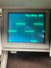
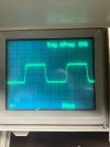
Square waves at 1 and 10khz. A real testament the the quality of these Peerless OPT’s.
No global feedback.

Ron
 
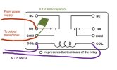
Dave sent me a link for a relay such as this.

Although not rated for high B+ voltages, Dave said he has never had a failure due to high voltage across the contacts.


View attachment 3477855

With the relay, is this the correct wiring? The red lead from the power supply to the NO terminal, the output transformer main to the COM terminal, with the capacitor bridging them? Is there a benefit to connecting the leads across both NO and both COM terminals?
 

Attachments

  • Untitled.jpg
    Untitled.jpg
    25.5 KB · Views: 12
With the relay, is this the correct wiring? The red lead from the power supply to the NO terminal, the output transformer main to the COM terminal, with the capacitor bridging them? Is there a benefit to connecting the leads across both NO and both COM terminals?
Your wiring is correct. Paralleling both NO/COM terminals will give you double the current capacity, which is not needed, but would not harm anything. I would use a 600VDC rated cap for a long life.
 
@dcgillespie - I'm not sure how I missed this thread, but it's fascinating for sure. How would you compare this modified version of the W-5M to your completely modified "Mullard" version that I build a few years ago - "Gillespie W-5M"? The performance specifications appear to be similar as expected, but it would be interesting to know how they compare in the listening test.....
 
I’ve rebuilt 3 pair with Dave’s latest scheme. Very high resolution but with the tube ease that the best tube amps have. It’s a little complicated but not bad. One more pair to go.
 
I set my rear panel up a bit differently. I saw an impedance selection scheme posted by @TriodeLuvr and decided to try it. This lets me use regular binding posts for the speaker cables. When I check bias I can still do balance across the test points and current can be made from the left test point to the black/common binding post. If I want to check the other tube I can move the selector to 16 ohms and use the red binding post. I don't much like the old terminal strips used for speakers. I drilled out two of the original holes for the terminal strip, which are conveniently on 3/4" centers if I want to use a dual banana plug, but can always reinstall the original strip and the holes will be covered. The only issue with this scheme is getting the octal shorting plugs as they aren't too common. Mine came from ebay. This works on the W5 handily since there is already an octal socket in proximity to the terminal strip.

View attachment 3540969
Where was this posted? I’d love to take a look at it.
 
I'm looking for someone within an hour or two driving distance of Grand Rapids, MI to do the full modification outlined in this thread on a pair of W5M's I picked up last year. I was planning to DIY, but my new business has taken over my small workspace and all of my time. I'd love to hear these amps play to their full potential. Thanks!
 
Back
Top Bottom