• The move to the new server is done. There are some software and database maintenance updates in process. This has us passing the hat around to help out. We appreciate any donations. Seriously, even a dollar helps. The payment page may be found here - https://www.audiokarma.org/support.html

Untapped Potential: Heath's W-5M

I’m looking at the schematic in post #2 of the use of this relay. It appears that there is no delay mechanism except for the fraction of a second it take for the AC relay coil to magnetize enough to pull close the NO contacts. Am I understanding this correctly? I guess that fraction of a second delay is sufficient in this application?
 
I’m looking at the schematic in post #2 of the use of this relay. It appears that there is no delay mechanism except for the fraction of a second it take for the AC relay coil to magnetize enough to pull close the NO contacts. Am I understanding this correctly? I guess that fraction of a second delay is sufficient in this application?

The relay isn't to delay B+, instead what it's used for is to disconnect B+ when the amplifier is shut off, to remove a powerful low frequency oscillation which happens during shut down, and therefore protect the output transformer. It's an issue unique to this amplifier. It's cool that Dave figured this out, it will likely save some of our precious transformers!
 
I know that Audio Research made an amp with the A470 opts that used the secondaries for cathode feedback and I think I remember Dave mentioning this. I'm also curious about the Heath AA-100 outputs suitability for cathode feedback.
I wondered if you made any progress on this question regarding the suitability of the Heath AA-100 OTs in the partial cathode feedback configuration. I have a spare set that I would like to use in this manner if it is worthwhile.

These AA-100 outputs are much more abundant that the W5-M output transformers and of similar specifications. I wonder if a AA-100 based W5-M would work with Dave’s modifications? Or does the magic emanate from the Peerless output transformers only. Of course some tweaking of feedback will be required.
 
Last edited:
John — The easiest way is to look at a 1 watt 10 kHz square wave on the output of the amplifier. Other than for amplitude, the display should appear absolutely identical on each output tap — not similar — identical. If it does, then the transformer will remain stable when used in a partially cathode coupled output stage.

I hope this helps!

Dave
Dave,

Just a check to make sure I understand correctly how to assess an output transformer (with secondary taps for C, 4, 8 & 16 Ohms) for suitability in CFB configuration using the secondary.

When you look at the 10 kHz square wave outputs what exactly are you comparing? I expect the amplitude and square waveform of terminals 4-C and 4-16 should be identical, except they will be out of phase, if you have the original secondary labeled C, 4, 8, 16 Ohms, where 4 is now grounded in CFB configuration.

So, allowing for phasing I think you should find identical the amplitudes and waveforms of secondary terminals 4 to C and 16 to 4 outputs.

Did I get this right?
 
Last edited:
Seems like you could connect the two channels on a scope, invert one and then overlay the traces. Based on Dave's description the two traces should like up exactly if the transformer is ok for cathode feedback.

My main problem getting this done, other than all my other projects, is patching them into an amp to get a good primary signal into the transformer. I don't really want to tear into one of my working amps to do this. I have another pair of W5's waiting for restoration. Maybe I could leave off the Peerless OPT and temp the Heathkit in for a test. Just wondering at this point. I'll look through my working amps and think it over. Maybe one of them wouldn't be too hard to temporarily connect the Heathkit.
 
Last edited:
A visual check has been sufficient for every transformer I’ve checked. Use a 10 kHz square wave, and use even a single channel scope to check for an identical presentation — other than for amplitude — at all three output taps. Best to load the 16 Ohm tap and check under feedback conditions so as to get the best presentation of supersonic frequencies.

Dave
 
A small suggestion, it would be helpful to have the test point voltages on the schematic for setting bias. I had to go reading through the thread to find them at the end of post #13. I will edit them onto my copy.
Thanks again for the great project and for the help with my questions.
John
I am reviewing the thread to make sure I have all the information needed as I work on my W5-m modification. I‘m unclear regarding the bias setting procedure partially addressed in post #13 with these measurements. My apologies if I missed it somewhere else.
Test Point Voltage

16458 Transformer = .061 vdc +/- 2%.
16309 transformer = .067 vdc. +/- 2%.
This does not explicity state where this measurement is to be made. I have the 16309 transformer set and assume this measurement is made from the test point (i.e. the cathodes of the power tubes) to the former 4 Ohm connection on the secondary (now grounded). So, this voltage is generated by the current through the 1 Ohm resistor connected to the cathode plus the resistance through one half of the secondary?

What is the target cathode current? Is this current the same for both transformer types? I assume the measured voltage is different for the two types of transformers due to the difference in DC resistance of their secondaries.
 
Last edited:
You’re correct on all assumptions — the voltage is measured from the TPs to ground to set the correct bias current — and across the TPs for DC balance. The different voltage levels account for the slightly different DC resistance of the two transformer secondary windings. I think the actual quiescent current is given up (later) in the actual presentation portion of the thread. If not, I’ll post it when I get home next week.

Dave
 
I have it in my notes as 43.6mA. I measure across the 1 ohm resistors from each test point to either the 16 ohm or 0 ohm terminals and measure bias current directly.

edit: found this reference in post 11 to 41mA.

Post 10 mentions 43.6mA

I guess it is probably ok to set it somewhere between 41 and 44mA. Setting the bias according to the specified bias test point voltages and then measuring across the 1 ohm resistor will tell.
 
Last edited:
This is great! We set our bias according to measured voltage between the cathode test points to ground (in my build with 16309 transformers = .067 vdc. +/- 2%), check between the two test points to aim for zero voltage, and then verify the actual cathode currents (41-44 mA) across the 1 Ohm resistors.

P.S. Thank you for pointing out those posts (#10 & 11). I missed that but remember now that I read it a while ago.
 
Dave also specified installing a jumper wire between the 0 and 16 ohm terminals in post 11. I think this is to put the two halves of the OPT secondary in parallel to even them out for bias current measurement and would be necessary to get his specified bias voltages. I just measure across the 1 ohm resistors one side of which is connected from the TP/cathode and the other to either the 16 or the 0 speaker terminal. If I have the amp open I just clip across the resistor.
 
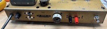
I set my rear panel up a bit differently. I saw an impedance selection scheme posted by @TriodeLuvr and decided to try it. This lets me use regular binding posts for the speaker cables. When I check bias I can still do balance across the test points and current can be made from the left test point to the black/common binding post. If I want to check the other tube I can move the selector to 16 ohms and use the red binding post. I don't much like the old terminal strips used for speakers. I drilled out two of the original holes for the terminal strip, which are conveniently on 3/4" centers if I want to use a dual banana plug, but can always reinstall the original strip and the holes will be covered. The only issue with this scheme is getting the octal shorting plugs as they aren't too common. Mine came from ebay. This works on the W5 handily since there is already an octal socket in proximity to the terminal strip.

W5 rear panel imp selector.jpg
 
I set my rear panel up a bit differently. I saw an impedance selection scheme posted by @TriodeLuvr and decided to try it. This lets me use regular binding posts for the speaker cables.
This technique also really pays off when it's applied to an output transformer with multiple interleaved secondaries. That's what prompted me to search for a better method years ago. A complex wiring arrangement in a stereo amp might require two octal plugs (one for each channel), but IMO that's still preferable to a switch or terminal strip jumpers. It's real luck that your amp had an octal socket you could repurpose!

Jack
 
It's real luck that your amp had an octal socket you could repurpose!
And that it was within reach of the OPT wiring. I have some W4's too but the octal plug is at the opposite end of the panel. I'd have to extend all the OPT wires. Maybe it would still be worth it. Anyway, thanks for sharing the idea.
 
Dave also specified installing a jumper wire between the 0 and 16 ohm terminals in post 11. I think this is to put the two halves of the OPT secondary in parallel to even them out for bias current measurement and would be necessary to get his specified bias voltages. I just measure across the 1 ohm resistors one side of which is connected from the TP/cathode and the other to either the 16 or the 0 speaker terminal. If I have the amp open I just clip across the resistor.
I puzzled by the requirement of the jumper between 0 and 16 Ohm terminals. You are right of course that the effect would be to add the average DC resistance of the two halves of the secondary, rather than the actual resistance of the relevant secondary half, to the 1 Ohm resistor to measure the voltage at the cathode of the power tubes. But wouldn’t you want the actual resistance of the relevant secondary half added to set the acquiescent current for a particular power tube?

Perhaps we are missing something. But like you, I will adjust bias to get the specified current through the 1 Ohm resistor, based on the voltage measured directly across it, at least until I am comfortable with the ”remote test points”.
 
Perhaps we are missing something. But like you, I will adjust bias to get the specified current through the 1 Ohm resistor, based on the voltage measured directly across it, at least until I am comfortable with the ”remote test points”.
Seems to me this was done simply to avoid the measurement being affected by the additional voltage drop created by the secondary DCR. I agree that measuring directly across the resistors is the best approach. Another option for easier future measurements would be to measure the secondary DCR with a low-ohms meter, then replace the cathode resistors with precision values that total 1Ω (or perhaps 10Ω). The measurement from the test point to ground would then be accurate as long as nothing is connected to the speaker terminals.

Jack
 
But wouldn’t you want the actual resistance of the relevant secondary half added to set the acquiescent current for a particular power tube?
I believe this additional resistance in series with the cathode would have an insignificant effect on bias and idle current. It mostly just affects the measurement itself.

Jack
 
Back
Top Bottom