

You are using an out of date browser. It may not display this or other websites correctly.
You should upgrade or use an alternative browser.
You should upgrade or use an alternative browser.
Untapped Potential: Heath's W-5M
- Thread starter dcgillespie
- Start date

By the way, seeing several of those power supply boards in your W5 rebuilds, I meant to ask (not related to the oscillation you reported above), are you dealing with the turn on surge, or in other words the higher voltage that would occur on those down stream caps right on startup, or if the frontend tubes were removed and then the unit is powered on? Meaning I didn't see the Zener string solution that Dave used in your pics. Maybe they are there, or some variation of them, and I just missed seeing it. So just wondering how you're dealing with that, if at all with these Sheldon Stokes boards?
That mod to the cap board doesn't "seem" like it would have any significant impact...?
The next question I might ask is if you temporarily disconnect the global feedback, what happens? (I expect it will stop oscillating). Maybe try that with and without the local loop feedback around the output stage. In other words is there an open-loop configuration you can fall back to as a starting point that produces stable output?
The next question I might ask is if you temporarily disconnect the global feedback, what happens? (I expect it will stop oscillating). Maybe try that with and without the local loop feedback around the output stage. In other words is there an open-loop configuration you can fall back to as a starting point that produces stable output?

Opening the GNF loop made no change. Pulling the first tube doesn’t stop it nor does then pulling the driver tube. It only stops when I cut the B+ to the output stage. I have triple checked the wiring of the OPT including the cathode feedback. At a loss for what to try next. Disconnecting the cathode feedback would be a bit of a pain but I may have to do it. Anyone ever hear of the plate leads being mis-color coded?

Opening the GNF loop made no change. Pulling the first tube doesn’t stop it nor does then pulling the driver tube. It only stops when I cut the B+ to the output stage. I have triple checked the wiring of the OPT including the cathode feedback. At a loss for what to try next. Disconnecting the cathode feedback would be a bit of a pain but I may have to do it. Anyone ever hear of the plate leads being mis-color coded?
Not with the Peerless OPTs, I haven't. To suggest the obvious, have you measured the resistance of the primaries? Sometimes the screen taps are the ones that get damaged or are partially open... I suppose it's also possible that the secondaries are out of spec, which would cause problems with the cathode feedback. Can you disconnect the CFB without mucking up the circuit? I'm not up to speed on this mod. ;-)
I disconnected the CFB and connected the 1 ohm cathode sense resistors to ground. No change. I also thought maybe it was environmental so I put the bottom plate on. Nothing there either. Starting to run out of ideas.
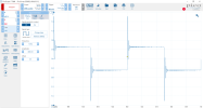
The oscillation makes the edge of a sine or square fuzzy in a random sort of way causes a bit of dancing of the trace. Looks like this on the spectrum plot.

The oscillation makes the edge of a sine or square fuzzy in a random sort of way causes a bit of dancing of the trace. Looks like this on the spectrum plot.
Hmm might be time to measure the output transformers. Both DCR and impedance.
The other thing you might try is to disconnect the B+ supply from the output of the rectifier tube and power the high voltage DC the amp needs from a bench power supply. Even if you can’t get it up to the 500V it requires it would still be telling.
Of course the other thing is the negative bias and the screen voltages. Stating the obvious but it’s got to be one of the OPT, the screen supply, the B+ supply, or the bias supply.
The other thing you might try is to disconnect the B+ supply from the output of the rectifier tube and power the high voltage DC the amp needs from a bench power supply. Even if you can’t get it up to the 500V it requires it would still be telling.
Of course the other thing is the negative bias and the screen voltages. Stating the obvious but it’s got to be one of the OPT, the screen supply, the B+ supply, or the bias supply.
Last edited:
Interesting development. I normally do not connect the audio common to chassis for what I believe will be noise causes. I thought I should try it so I connected a 10ohm 5W resistor from the audio common bus to chassis. The 50kHz hump is gone and 1k and 10k sines look very good. But now the 1k and 10k square waves are out of control. The 1k has a huge overshoot and some ringing but the 10k is so wild it almost isn't recognizable. I'm at a loss how connecting the chassis could clean up the sines but ruin the square waves.
COM is not circuit ground like it was in the original design. If your scope is connected between 16 and COM, it will connect COM to the mains ground (if your scope has a three prong plug). That could create an erroneous scope trace. Try lifting mains ground off of the chassis on the amp, and also lifting mains ground from your scope (temporarily) to obtain a valid reading. That’s what I needed to do, anyway, to get a valid scope trace.
I'm using a Picoscope which is USB connected to my laptop. I think ground on the Pico is isolated from power ground but I'll have to verify. I was getting good square waves earlier before the connection of the signal common bus to the chassis. Thanks for sticking with me on this. I did try a cheater plug on the amp power to break the power ground connection to chassis but nothing changed with that.
Wonder if I should start another thread for my troubleshooting rather than mucking up the original thread. I've kept writing here since I'm installing the mods described by Dave but maybe I should take my troubleshooting to a new thread. Anyway, too late today for any more work. After coffee tomorrow.
Thanks,
John
Wonder if I should start another thread for my troubleshooting rather than mucking up the original thread. I've kept writing here since I'm installing the mods described by Dave but maybe I should take my troubleshooting to a new thread. Anyway, too late today for any more work. After coffee tomorrow.
Thanks,
John

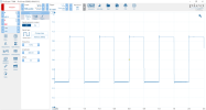
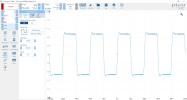
kward gets the prize. Even though my Picoscope is USB to the PC, the ground clip on the probe connected to speaker COM was fouling the measurement. It also through the bias balance adjustment off. Moved it to the signal common bus, adjusted bias and balance and bingo. Everything seems ok. User error with the measurements. I either need to drink more coffee or less. Thanks for all the advice and comments.
Would this have happened if I had used my Tek bench scope and floated the power ground pin?
John

Would this have happened if I had used my Tek bench scope and floated the power ground pin?
John
I guess I figured the Picoscope was floating since there isn't a direct power connection to ground. Not correct. Must be some common side connection into the laptop. I do notice they sell active differential probes which would probably work in this case but the 700V version, lowest rating, is almost $500. I can probably get along without it for most things although I'm hesitant to touch my probes to higher voltages even on 10:1. I should probably get a 100:1 probe for power supply testing.
Aren't there USB ground-isolation devices?