• The move to the new server is done. There are some software and database maintenance updates in process. This has us passing the hat around to help out. We appreciate any donations. Seriously, even a dollar helps. The payment page may be found here - https://www.audiokarma.org/support.html

Untapped Potential: Heath's W-5M

In this case, if an AC balance pot were to be employed, I believe the pot would sit in the lower leg of the split load inverter between the cathode resistor and ground, therefore up from ground by only the voltage produced by the current through that 5K pot.

In any case, I appreciate and understand the complexities of this. I'm thinking through this cuz I just don't know if I'll be able to source tubes that are that well matched between the triodes in the driver stage as well as the output stage. I do believe the output transformers are very well balanced, both primary and secondary, but if I can't get tubes that are well balanced then what good does a highly balanced OPT do? Anyway, just thinking through it all right now.
 
you could technically put it on either side, but sanity would place it on the cathode side because of the lower voltage.
 
In this case, if an AC balance pot were to be employed, I believe the pot would sit in the lower leg of the split load inverter between the cathode resistor and ground, therefore up from ground by only the voltage produced by the current through that 5K pot.

In any case, I appreciate and understand the complexities of this. I'm thinking through this cuz I just don't know if I'll be able to source tubes that are that well matched between the triodes in the driver stage as well as the output stage. I do believe the output transformers are very well balanced, both primary and secondary, but if I can't get tubes that are well balanced then what good does a highly balanced OPT do? Anyway, just thinking through it all right now.

I really wouldn't worry about it too much. My Williamsons do not have balance pots on the phase splitter or the driver stage, and produce .1% distortion at 1 watt and less than 1% distortion at 20 watts.
 
In a phase splitter stage that is direct coupled from the previous stage -- safety issues aside -- the ideal place to include an AC Balance control is in the plate leg, since its placement there will cause minimal change to the operating point of the stage with adjustment. When placed in the cathode leg, adjustment will of course vary the AC balance as expected, but also impact the operating point of the stage due to varying the bias on the tube as well. From a practical standpoint, in any quality design, the safety advantage of placing the control in the cathode leg may well outweigh the theoretical advantage of placing it in the plate leg, but in theory, the point still stands.

Dave
 
this is fantastic. it is above my technical understanding, but i am learning as i go. i appreciate the opportunity this provides, and im really enjoyin the DG SE-1 i recently finished.

thank you for all this.
 
Last edited:
I really wouldn't worry about it too much. My Williamsons do not have balance pots on the phase splitter or the driver stage, and produce .1% distortion at 1 watt and less than 1% distortion at 20 watts.
My Williamson build did not include the typical balance pot in the output tube grid/cathode circuit and balance seems to be fine according to test data. I swapped in/out 30 1625 tubes and distortion numbers varied vary little. I am using a single wire-wound 325 ohm/25W cathode resistor.
 
the other thing with a split load inverter, if the plate and cathode resistors match, the output will be equal so long as the tube isn't just really smoked. Lots of local feedback with that un-bypassed cathode resistor will correct for a fair bit of variation in the tubes.
 
In a phase splitter stage that is direct coupled from the previous stage -- safety issues aside -- the ideal place to include an AC Balance control is in the plate leg
Ah yes, I hadn’t considered the direct coupled nature of the phase inverter. Hmm.
 
If I may, the real beauty of the split load inverter is that as long as the plate and cathode loads are equal -- I say loads in the plural sense to include the complete coupling circuits at both the plate and cathode elements: the actual load resistors, the coupling caps, and the following stage load resistors -- then the dynamic output from each side of the inverter will always be exactly equal, regardless of the condition of the tube used. This is the real beauty of the configuration. The tube used can age to the point of no emission what-so-ever, but the outputs will remain exactly equal at all times throughout the emissive life of the tube. Performance will obviously obviously be severely compromised with a poor performing tube installed, but at least both outputs will perform equally poorly.

This is why this type of inverter will always perform best when used in a Williamson design, where the load presented by either side of the following (driver) stage will virtually never change -- this because the driver tube is never driven positive in such designs.

Looking back "into" the outputs from this inverter, the cathode leg does indeed present a lower drive impedance than the plate side does This characteristic only becomes important however if the impedance of the following stage grid loads is altered, as would be the case if the inverter is used to directly drive an output stage into grid current.

I hope this helps!

Dave
 
80-odd years ago, and whilst quite young, Williamson appreciated that dc and ac balanced operation were both needed to keep harmonic distortion low, and allow stable operation with feedback, without low and high frequency influences ruining the outcome. It may not take much to upset that outcome, as many soon came to appreciate. And fortunately we have come full circle and can now recreate a 70-80 year old amp that avoids the pitfalls that many fell into of their own doing along the way, as well as enhance stability along the way.

The pot in the driver stage B+ feed is imho the simplest and best way to manage ac imbalance if one knows that they aren't or may not be using matched driver or output stage valves, or doesn't want to make the effort to match resistor and capacitor values, or just wants to get the most out of what they have.
 
The pot in the driver stage B+ feed is imho the simplest and best way to manage ac imbalance if one knows that they aren't or may not be using matched driver or output stage valves
Great, thank you. I was wondering if that would be the better place to place the AC balance control. Still, not sure I'm going to worry about it too much, as others have pointed out. Only if it's a real problem will I feel compelled to address it.
 
16309's on the recent 3 amps. I got one a month or two back with a bad 309 and found a 458 online. I'll match it up someday or find another 309 and sell the 458 to a friend who wants a spare.
I received another 16458 OPT today. Now I'm ready to make a 309 pair and a 458 pair. I have one more small project to finish and then I'll start on the W5's.
 
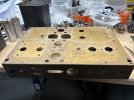
Here we go again. First pair will be the 16458 outputs. It isn't purty but I'm not inclined to repaint and lose the markings. I'll just go with however the "patina" evolves. If anyone has a suggestion about cleaning without removing the markings let me know.
Thanks
W5 16458 first unit.jpeg
 
My Williamson build did not include the typical balance pot in the output tube grid/cathode circuit and balance seems to be fine according to test data. I swapped in/out 30 1625 tubes and distortion numbers varied vary little. I am using a single wire-wound 325 ohm/25W cathode resistor.

What I like about the Williamson arrangement is the added bit of grid bias that helps stabilize the output tubes.
 
Here we go again. First pair will be the 16458 outputs. It isn't purty but I'm not inclined to repaint and lose the markings. I'll just go with however the "patina" evolves. If anyone has a suggestion about cleaning without removing the markings let me know.
Thanks
View attachment 3387402
I've have decent results from a magic eraser on a Scott 222 and an LK48 chassis. It doesn't get rid of all the corrosion but does a good job removing a bunch of stains and generally cleaning up without damaging the lettering. I get the eraser damp and do a light pass, then test some harder scrubbing on an area in the back where I don't mind possibly losing a little lettering, but it hasn't been a problem so far.
As a side note, I'd love to see progress pics of your build. I want to do the mods on a pair of W5M's I recently acquired but it would be my first time going straight from a schematic with no pictorial assistance and I'm scared.
 
Hi pingpong,

Thanks for the suggestion. I did use a magic eraser and it helped a small bit but they just aren't going to be beautiful. I don't mind a bit of age and patina.

Dave attached a photo of his W5 internals at the end of post 15. I posted a couple pictures of mine in this thread as I remember. My built is a bit different as I used capacitor PC boards designed by Sheldon Stokes rather than buying new can caps or restuffing them. This board fills up quite a bit of space under the power transformer. Probably better to follow Dave's lead with his layout. I'll share any of my pictures that might help. I've done two pair for friends, one of which uses the power supply pc boards. The other was already "restored" so I only modified what needed to be done. I have good pictures of both projects.
Johh
 
What I like about the Williamson arrangement is the added bit of grid bias that helps stabilize the output tubes.
I like cathode bias due to its simple and reliable nature. I can easily live with 20~25 watts RMS output with my +100dB efficient loudspeakers. The HF-87 replica amp I built also sounds good (from a power output standpoint), but I can't really hear the extra 10 watts it affords. I like it just the same due to the nostalgic era it represents.
 
Here we go again. First of the current pair which are mine rather than for friends. I used the Sheldon Stokes cap board again. Had to make one small adjustment to the original traces to accommodate the revised power supply for this version. Makes for a full chassis but I like it. All DC voltages spot on at 120VAC in. Haven't gotten beyond this initial startup including bias/balance adjustments. I used some small transformers for the bias supply that are a bit higher in voltage so had to short the 4.7k resistor feeding the bias pot to get more voltage drop and get the range workable. Probably can tweak it a bit more. I'll need to buy a quad of 6L6GC or others of that ilk. I have a nice pair of old stock 7027a's that I used for the startup.

working first test.jpeg
 
Not the best start I've had with an amp. The other 4 I've rebuilt started and behaved perfectly. This one has an oscillation that my FFT indicates is centered just under 50kHz. Not more time right now. Back to it later. I'll try swapping some tubes just to be sure. Then I'll have to dig in.
 
Back
Top Bottom