• The move to the new server is done. There are some software and database maintenance updates in process. This has us passing the hat around to help out. We appreciate any donations. Seriously, even a dollar helps. The payment page may be found here - https://www.audiokarma.org/support.html

Untapped Potential: Heath's W-5M

Did you ever get this resolved? The numbers you are posting are honestly not possible in a real world scenario, since the supply voltage is no more than about 125 vac maximum. I just measured the AC voltage from the chassis of each of my amplifiers to a known AC ground while operating from a 117 vac source with nothing more than speakers connected. One returned a reading of 0.2 vac, and the other 0.4 vac.

I suspect you have fallen into that frustrating realm where something you think is true is actually not. My first guess would be that the AC ground you are measuring to is really not an AC ground. Or that your meter is supplying a false indication. The bottom line is that it is simply not possible to have a real 170 to 240 volts AC appearing on the chassis of your amplifiers (relative to AC ground) and yet have them otherwise working great. At the very least your interconnects would either be fried, other equipment connected to the amplifiers would be fried, or worse, you would be fried.

I would start from the beginning by absolutely verifying that the AC ground you are measuring to is in fact a true representation of your home's AC power system ground -- I mean verifying it all the way back to the breaker panel where true ground relative to the hot legs originates from. With the kind of work I've seen over the years, I take nothing for granted regarding this. At the very least, get one of those testers that verifies that the receptacle you're using is in fact connected properly so that hot is truly hot, neutral is truly neutral, and ground is truly ground. Then verify the accuracy of your meter.

I've had lots of experience with these types of problems before -- not this exact problem, but one where things just don't add up and don't make any sense. The one thing they all had in common though -- without exception -- is that in every case, something I thought was true, was not. Dollars to donuts that's the same thing you are dealing with here as well.

Let us know!

Dave
 
Did you ever get this resolved? The numbers you are posting are honestly not possible in a real world scenario, since the supply voltage is no more than about 125 vac maximum. I just measured the AC voltage from the chassis of each of my amplifiers to a known AC ground while operating from a 117 vac source with nothing more than speakers connected. One returned a reading of 0.2 vac, and the other 0.4 vac.

I suspect you have fallen into that frustrating realm where something you think is true is actually not. My first guess would be that the AC ground you are measuring to is really not an AC ground. Or that your meter is supplying a false indication. The bottom line is that it is simply not possible to have a real 170 to 240 volts AC appearing on the chassis of your amplifiers (relative to AC ground) and yet have them otherwise working great. At the very least your interconnects would either be fried, other equipment connected to the amplifiers would be fried, or worse, you would be fried.

I would start from the beginning by absolutely verifying that the AC ground you are measuring to is in fact a true representation of your home's AC power system ground -- I mean verifying it all the way back to the breaker panel where true ground relative to the hot legs originates from. With the kind of work I've seen over the years, I take nothing for granted regarding this. At the very least, get one of those testers that verifies that the receptacle you're using is in fact connected properly so that hot is truly hot, neutral is truly neutral, and ground is truly ground. Then verify the accuracy of your meter.

I've had lots of experience with these types of problems before -- not this exact problem, but one where things just don't add up and don't make any sense. The one thing they all had in common though -- without exception -- is that in every case, something I thought was true, was not. Dollars to donuts that's the same thing you are dealing with here as well.

Let us know!

Dave
Thanks Dave, that sounds like a good plan!
 
Just gearing up to do my 3rd pair. Have more parts to order. Also just replaced a failed power transformer in the first pair I did for a friend. Got it going today. The next project, the 3rd pair, will be for me. Will make a nice set with my DaveG W3’s and W4’s
 
I have two W-5M units with Gillespie's design. They have been in service since July (usage of 3-6 hours/day). I wanted to re-adjust the bias and offset but I am unable to get the bias to the recommended value. The offset adjusts to 0.0V just fine.

On the Bias adjustment the maximum reading on the two amps are:
OPT 16309: 0.059V, Should be 0.067V
OPT 16458: 0.047V, Should be 0.061V
I could not adjust them any higher.

What needs to be done to be able to adjust the bias higher?
 
What voltage bias transformers did you install? You might have to adjust some of the bias circuit resistors. To get higher current you'll need a lower voltage.

Looks like you have one of each output transformer version.
 
Correct, I have one each OPT version.

The bias transformer voltage for both is 12.5V. In July of 2024 these adjusted perfectly when all was new. I'm thinking I would need to lower the 4.7K in the bias circuit (connected to the 10K pot).
 
The bias transformer on Dave's schematic is specified as 25.2VAC and 38VDC at the input to the bias circuit. Where did you measure 12.5V? I assume you mean DC volts.
 
The bias transformer on Dave's schematic is specified as 25.2VAC and 38VDC at the input to the bias circuit. Where did you measure 12.5V? I assume you mean DC volts.
Typing mistake. It is a 25.5VAC transformer at 115VAC input. My bias input voltage is 38VDC.
 
Since you can't get the bias voltage at the grids low enough to make the specified bias current I might ask if the tubes are old and weak. You can try clipping a jumper lead across the 4.7k that connects to the wiper of the pot. That should temporarily get the range to a lower voltage so you can see if it raises the bias current enough.
 
Wow!

This is an amazing investigation and write up.
I just picked up the first of two W-5Ms from a 90yo who built them during college. The first one had the 309 OT. I assume the second will also.

Did anyone ever assemble a parts list for this W-5M mod?

thanks!

Kelly
 
Since you can't get the bias voltage at the grids low enough to make the specified bias current I might ask if the tubes are old and weak. You can try clipping a jumper lead across the 4.7k that connects to the wiper of the pot. That should temporarily get the range to a lower voltage so you can see if it raises the bias current enough.

The other thing that does this is low screen voltage.

but yeah, if the B+ stuff is happy and the grid voltage is where it belongs, tired tubes are a reasonable conclusion, unless its just output tubes that bias a little strange. Some new production ones don't bias like old ones do. If thats the case, making the 4.7k in series with the 10k bias adjust pot smaller will make the supply less-negative and bump the current through the tubes. I wouldn't go so far as to jumper it out entirely, but maybe a 15k across it.
 
The JJ 7027a is the same as their 6L6GC according to Eurotubes so they only stock the 6L6. I’ve rebuilt two pair of these and used 6L6GC in both. They work just fine. I suspect Dave used them because he had them.
 
@dcgillespie

Hi Dave,

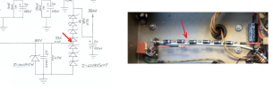
I'm trying to reconcile the filament bias portion of the schematic with your reference wiring image:

1730391650740.png


For the two red arrows in left vs right picture, it looks like you've tapped into the Zener string at 2x up from ground in the reference wiring picture, but the schematic shows it being tapped 3x Zeners up from ground. Am I seeing this correctly? I assume the key point is to deliver ~85V DC as the filament bias voltage.

I'm also wondering what is the purpose of the 100V Zener? I expect it is to keep the surge voltage down to no higher than 100V on startup?

Wonderful writeup. You could publish a book with all of your improvements for all the amps you've improved and documented on AK over the years! I would buy a copy!

with regard,
Kevin
 
Hi Kevin — Thanks so much for the kind words!

All your assumptions are correct. The main zener string only conducts full current at start up, at which time the voltage at the heater bias tap even after the divider resistors would normally exceed 100 vdc. The 100 volt zener at the tap then acts to limit the heater bias to no more than 100 volts during that time. When the B+ at the top of the main zener string then falls to its normal operating value after the tubes warm up, then all current through the zeners below the bias tap and at the bias tap ceases, and the only current through the zeners above the bias tap is that which flows through the 33K and 47K heater tap divider resistors, which then allows the heater bias to drop to its nominal value of 85 vdc.

As for the discrepancy between the schematic and the wiring shown in the underside pic you reference, that’s simply because I used what components I had on hand, but specified commonly available values on the schematic for anyone interested in duplicating the work. The components I actually used required the tap to appear at the top of the bottom two zeners in the main string, and also required slightly different divider resistor values as well.

I hope this helps!

Dave
 
Another question Dave,

Sometimes it's helpful to add an AC balance control on the inverter. I recall you doing that on one of your other "improvement" threads, a Fisher perhaps. But I see an AC balance adjustment is not offered in this design. Was that something you considered and found not to be needed? I'm thinking it may not have been needed because of the balanced feedback added to the output stage, which might minimize those down stream differences after the inverter? But I assume it's still important to use as closely matched triode sections as possible on the driver stage?
 
Hi Kevin -- It's always a challenge to know how far to go, and where to stop with a given modification. With this project, I was very aware of still trying to keep the amplifier's identity as a W-5M in tact, and I knew I was already pushing that envelope with the modifications I was presenting. But, the improvement was so significant that I felt it was justified, touching dependability and component life, as well as measured and audible capabilities. In the course of developing the modification, I did in fact look at the impact that adding an AC balance control would have, but frankly, it was so little that I deemed the impact of adding such a control not worth the effort. Now my examples used well matched tubes and passive components in the push-pull sections of the design, and the OPT (either version) is a wonderfully balanced design, so mine were hardly an environment where such a control would provide significant aid. But even when I would purposely mis-adjust the control, it hardly produced a major impact on the low distortion readings that a balance position provided, which I largely attribute to the partially cathode coupled output stage connection. So, I ultimately abandoned the idea of adding an AC Balance control to the modification. Now if the push-pull sections were not nearly so well balanced as mine were, the results may be different, allowing such a control to have good effect, but I have no knowledge regarding that.

I hope this helps!

Dave
 
Balancing would also burden the user with the need for at least a THD meter, or better still a spectrum analyser, to appreciate what any pot twiddling would achieve when the feedback was temporarily disconnected. I note that Williamson ditched that pot between the original version and the 'new' version - perhaps as many would be using new valves in their builds, and identifying any affect could be quite difficult, even for someone lucky enough to have a scope back in 1948.

There is also the issue of safety, given that the pot sits at 400V+. I recently came across an early commercial W where the pot was purposefully insulated from the chassis, but the metal pot shaft was live (!), so they had only been able to source an 'uninsulated' pot at that time, even though another equally vintage amp used an insulated pot. I tweaked the distortion using that pot, but didn't make a note of the range of harmonic distortion variation available.
 
Back
Top Bottom