

You are using an out of date browser. It may not display this or other websites correctly.
You should upgrade or use an alternative browser.
You should upgrade or use an alternative browser.
Untapped Potential: Heath's W-5M
- Thread starter dcgillespie
- Start date

Thanks all. I'll give it another try at layout. I've thought of varying the height of the diodes alternating one low and the next high off the board. What about some sort of heatsink attached to the top of the diode array? Trying to save some space as I'm using an SDS labs power supply board instead of the can capacitors and it takes up a bit of room. I can go back to re-stuffing the cans if needed to make more room under the chassis.


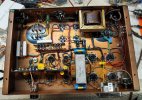
Here's how I did that, in a Fisher 55A amp that used Dave's mods. See the area just below and to the right of the round cutout for the output transformer.
There's actually two different Zener strings here, in this amp- one for the main B+, and one for the supply to the cathode follower driving the output tubes.
Regards,
Gordon.
There's actually two different Zener strings here, in this amp- one for the main B+, and one for the supply to the cathode follower driving the output tubes.
Regards,
Gordon.
I have the first of the pair finished and working. Only passed a few sines and squares so far but the 10k square wave looks like the example that Dave posted. I'll do more testing when the second is done. I used an SDS capacitor board so my layout is different. I made a small perf board for some of the EFB components.
@GordonW, your suggestion for mounting the zener diodes worked well. I mounted the twin terminal strips on top of a standoff to keep it above some other stuff. Made a small perf board for most of the EFB components and mounted it up on a standoff as well. I still have some detail cleanup to do but I'm glad it's functional.
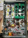
@GordonW, your suggestion for mounting the zener diodes worked well. I mounted the twin terminal strips on top of a standoff to keep it above some other stuff. Made a small perf board for most of the EFB components and mounted it up on a standoff as well. I still have some detail cleanup to do but I'm glad it's functional.
Last edited:

Nerd -- thanks so much for taking on these modifications. I think you will be very pleased with the outcome! Since the time I worked on my amps here, I have had significant trouble keeping them out of the rotation!
Regarding the zeners, one thing I am is very conservative when specifying such devices. It is so typical to see discolored, chard, and burnt circuit boards under where such devices reside -- a manner of operation I simply cannot accept.
Regarding the way I mounted them, it was simply the easiest way to safely and quickly mount them, as there are zero concern for the effects of any heat dissipation they create.
Finally, as you correctly mentioned, they are only conducting any significant current during the start up period, before the amplifier tubes have warmed up. But even then, I must emphasize that the zeners are so over specified, that you can leave the amplifier running indefinitely with all the amplifier tubes removed (just the rectifier tube installed), and the zeners will only become warm at best to the touch -- and I do mean truly only warm by human touch standards. They do not ever run hot at all under any condition of operation. Under normal conditions when all the tubes are installed, the heat they generate during the warm up period is so brief that you really cannot feel the effects of that heat temp wise on their bodies. When the amplifier is operating, the zeners generate virtually zero heat themselves.
The reason they run so cool -- even under worst case conditions -- is because they are 5W devices, with many lower voltage units connected in series to make up the total zener voltage. They really are a complete answer to the original cap eating over-voltage problem of the W-5's original design.
Dave
Regarding the zeners, one thing I am is very conservative when specifying such devices. It is so typical to see discolored, chard, and burnt circuit boards under where such devices reside -- a manner of operation I simply cannot accept.
Regarding the way I mounted them, it was simply the easiest way to safely and quickly mount them, as there are zero concern for the effects of any heat dissipation they create.
Finally, as you correctly mentioned, they are only conducting any significant current during the start up period, before the amplifier tubes have warmed up. But even then, I must emphasize that the zeners are so over specified, that you can leave the amplifier running indefinitely with all the amplifier tubes removed (just the rectifier tube installed), and the zeners will only become warm at best to the touch -- and I do mean truly only warm by human touch standards. They do not ever run hot at all under any condition of operation. Under normal conditions when all the tubes are installed, the heat they generate during the warm up period is so brief that you really cannot feel the effects of that heat temp wise on their bodies. When the amplifier is operating, the zeners generate virtually zero heat themselves.
The reason they run so cool -- even under worst case conditions -- is because they are 5W devices, with many lower voltage units connected in series to make up the total zener voltage. They really are a complete answer to the original cap eating over-voltage problem of the W-5's original design.
Dave
Hello Dave,
Thanks for writing. I'll be starting on the second unit today. Stripping and cleaning first.
I have a safety related question. On this amp I drilled out the RCA jack opening and installed an isolated jack. So far I haven't connected the audio ground to chassis. There is a power cord chassis ground to the green wire. Do I need to connect audio ground to the chassis or is it ok to let it float? I've seen articles about using a bridge rectifier with a resistor and cap as a ground break. Since these are for a friend, I can't be certain how they will be used in future and want them to be safe but not a cause for ground loop problems as well.
Thanks,
John
Thanks for writing. I'll be starting on the second unit today. Stripping and cleaning first.
I have a safety related question. On this amp I drilled out the RCA jack opening and installed an isolated jack. So far I haven't connected the audio ground to chassis. There is a power cord chassis ground to the green wire. Do I need to connect audio ground to the chassis or is it ok to let it float? I've seen articles about using a bridge rectifier with a resistor and cap as a ground break. Since these are for a friend, I can't be certain how they will be used in future and want them to be safe but not a cause for ground loop problems as well.
Thanks,
John
A small suggestion, it would be helpful to have the test point voltages on the schematic for setting bias. I had to go reading through the thread to find them at the end of post #13. I will edit them onto my copy.
Thanks again for the great project and for the help with my questions.
John
Thanks again for the great project and for the help with my questions.
John

One unit done and about half completed on the second. I ruined one of the EFB mosfets on the first and don't have another but I have a supply of STP3NK90ZFP 900v relatives. Seems like they should work ok but wonder if anyone sees a problem in this application that I haven't recognized.
Get the second amp working and my friend who owns the amps came over tonight to be part of the inaugural listening session. He is thrilled with them. They are very resolving but not in a harsh or unpleasant way. A great result for this modification. Thanks to Dave for this design upgrade. If you have W5's I think you should consider this improvement.
John
John
Hi John -- I really appreciate you're taking this project on! It's no small modification to make because in total, it's addressing so many issues. But I found the results to be so-so worth the effort, and still have trouble taking them out of my normal rotation now. There is just such a sense of presence, dynamics, and clarity combined with a smoothness that makes them so enjoyable to listen to-- and all without always cringing at the thought that they're destroying themselves every time I turn them on. I'm glad you both found satisfaction from your work and the modification. Independent verification is always the very best kind of verification to have!
Dave
Dave
Final report:
Spent that afternoon yesterday at a pal's house who has original restored W5's. He was anxious to hear them with the updates. Also with the friend for whom I built the amps. We mainly listened on a couple different pairs of UREI monitors, the 829 and 809 versions. These amps thrilled all of us on these studio monitor type speakers. My friend took them home and is now the proud owner. He also has a pair of UREI monitors so it was a good test. I also took a recently remodelled pair of Dynaco MK2's which use a 6SN7 board with auto bias. They acquitted themselves very well and came close to the W5's overall but couldn't quite match the easy level of very exquisite detail in the W5's. The W5's never gave up at the levels we played which was quite high a couple of times just to see how they would do. Great amps.
John
Spent that afternoon yesterday at a pal's house who has original restored W5's. He was anxious to hear them with the updates. Also with the friend for whom I built the amps. We mainly listened on a couple different pairs of UREI monitors, the 829 and 809 versions. These amps thrilled all of us on these studio monitor type speakers. My friend took them home and is now the proud owner. He also has a pair of UREI monitors so it was a good test. I also took a recently remodelled pair of Dynaco MK2's which use a 6SN7 board with auto bias. They acquitted themselves very well and came close to the W5's overall but couldn't quite match the easy level of very exquisite detail in the W5's. The W5's never gave up at the levels we played which was quite high a couple of times just to see how they would do. Great amps.
John
Since the W5's with 16309 ouputs have been running for a week or more, another friend with the later 16458 version wanted to get the same update so I'm almost finished with the first and have stripped the second and ready to start on it tomorrow hopefully. Just wish I had a pair of my own now.
The first of the 458 amps is working fine. One thing I had to adjust was the resistance value between the balance and bias pots. At minimum bias current I couldn't get below about 56mA. I added a 10k resistor in series with the 4.7k that's on the schematic and that gave a few more volts of neg bias at the grids but even that just reduced the bias current to the specified number. Seems like I would want to have some range both above and below. What might be the best solution. Grid bias right now is about -31V and the supply runs between -36 and -37 volts. Not much headroom left. I'm wondering if a higher voltage bias transformer might be the best solution.